
musicisair
Member
- Joined
- Nov 11, 2024
- Messages
- 60
- Likes
- 17
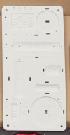
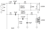
I'm building the CSS Audio's 3TD-X and was planning on laying out the circuits just like they are on their 3D printed board (see attached photos), and thought it'd be fun to replicate Gabster's crosstalk experiments.
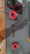
I have a small speaker wired to an 0.75mH air core inductor (litz wire , but I don't think that matters?). I'm generating a 2300Hz sine wave and sending the signal through my Motu M4 4x4's headphone jack at full volume directly into a 0.4mH air core inductor.
The 2300Hz signal from headphone out measures ~1 Volt and 80 μA (measured via a cheap Astro DM6000AR).
With both inductors laying flat, and spaced about 8 inches apart I can easily hear the sine wave from the speaker. So there seems to be significant crosstalk at headphone-out power levels at this orientation and distance. See attached photo (ruler measures 5 inches).
Does this test reveal real problems with the layout of the networks? Or in other words: should I deviate from the design to try find a more optimal arrangement/spacing?
(my related build thread)
Attachments
Last edited: