
-
WANTED: Happy members who like to discuss audio and other topics related to our interest. Desire to learn and share knowledge of science required. There are many reviews of audio hardware and expert members to help answer your questions. Click here to have your audio equipment measured for free!
You are using an out of date browser. It may not display this or other websites correctly.
You should upgrade or use an alternative browser.
You should upgrade or use an alternative browser.
32 Bit Float Explained
- Thread starter Eurasian
- Start date
NP. Please be aware that Amir kindly pulled many of the earlier posts over from another forum, so they are pushing 20 years old in some cases (and are based upon even earlier documents and notes). The fundamentals do not change, fortunately, but some of the info is less relevant these days. For instance, virtually all modern audio DACs resample asynchronously and isolate the clock from incoming jitter in the data stream, something rare when I wrote about that back then.@DonH56 Thanks for the links. I start reading...
HTH - Don
AnalogSteph
Major Contributor
"Virtually all"? The ESS ones do for sure, high-end TIs like PCM1792/94/95/96/98 possibly do (at least they have a propensity towards hard clipping at 0 dBFS, which is usually an indication), but PCM510x I'm pretty sure do not, and your average AKMs like AK4493 definitely do not either. Neither do CS4398s (not like you would expect it in a 20-year-old part), not sure about CS43198/CS43131.For instance, virtually all modern audio DACs resample asynchronously and isolate the clock from incoming jitter in the data stream, something rare when I wrote about that back then.
Fully agree. I wasn't supporing the need for floating point - though it does have some advantages in this application (for example being able to represent the captured voltage as it's actual numerical voltage, rather than some arbitrary scaling factor)If we define the peak voltage level as 10 Volts, 32-bit integer precision takes us down to around 2.5e-9 or 2.5 nano volts. Check my calculation: 32 bits * 6 dB = 192 dB; 10^(192/20) = 3.98e9; 10 / 3.98e9 = 2.5e-9.
How small is that? By comparison, theoretical Johnson/Nyquist noise of a 1 ohm resistor at room temperature over 20 kHz bandwidth is about 18 nano volts. The noise of most high quality opamps is also higher than this. So it appears 32-bit int has enough numeric precision, in absolute terms, no need for scaling or exponents. The limitation must be somewhere else, and apparently it is the dynamic range of ADCs.
PS: alternate computation: 32 bits give 4.29e9 values, 10 volts divided into 4.29e9 equal parts is 2.3e-9 or 2.3 nano volts each.
But I was answering. your question : "Why not simply set digital full scale to the max voltage the mic can produce?"
as : You might not know what that max voltage is - or you might not even be connecting a mic.
There is no limitation for data acquisition, it's mainly (but not only) done for user experience, namely: presenting a stronger signal, even above 0dBFS, to the end user. That inevitably requires floating point.So it appears 32-bit int has enough numeric precision, in absolute terms, no need for scaling or exponents. The limitation must be somewhere else
And this thread is now at least 3x longer than it needs to be, because we don't read the existing posts... There are even Julian Krause's videos posted where he explains this is in simple terms.
We could be wrong, of course. Only the manufacturers know why they did things a certain way, but they're too busy selling products to tell us the truth.
However, if you put all the pieces together, it makes perfect sense. And so we might see even single-ADC devices with DSPd floating point outputs, if the cost is low enough and the user demand is there.
Last edited:
I'm still stuck on this BeerBear. I've only done hobby electronics, Arduino, Pi, etc., but to my knowledge the principles are the same for all chips, even the most advanced ADC chip manufactured today. So if someone here has the technical knowledge I would like to hear it.That inevitably requires floating point.
Each chip has a pin. Through each a current can be input or output. If an analog voltage is applied it MUST not exceed a maximum voltage or it will fry the chip. The chip is designed to "read" that range of voltage, let's say 0 to 3v.
The miniature size of the chips doesn't make them the best choice to regulate that voltage so as much as can be done beforehand, the better.
As the voltage makes its way through the transistors, etc. of its internals, it is shunted off onto different conductive pathways tracks. There are many ways to do this, but at some point, the original voltage has set each track to an ON/OFF state, a 0 or 1. In the most simple ADC, it will have 8 tracks, each with a bit set on or off. At the point, the manufacturer can decide where to sent each of the 8 values through its own pin, or it can serialize those values, and send them through one pin with the user expecting them to followed a "clocked" protocol I2C, etc.
I'll make up the basic scenario. 1 pin sets a clock. 8 pins output the 1-byte word that is the digital "sample" of an input voltage measure at 1/48,000th of a second.
I can put that data to a DSP, to memory, whatever I want to do.
So, when many on this thread have said something like "but the user needs more dynamic range so uses 32-bit float" I have NO IDEA what they're talking about based on my understanding of ICs. Again, all I can do is read what comes out of the pins, which are either serialized, or in parallel, but still CLOCKED and PRECISE.
It's not that I don't understand how an IC can take a bit stream and convert it into floating point. That's TRIVIAL. "Float" is just a fancy name for SHIFTING BITS. In a sense, 100% of what an IC does is shift bits! So fine, shift the bits and output a 32-bit word in 32-bit float format.
Why would the ADC part of the chip shift the bits into floating point?
An ADC can only make On/Off decision about a current. It will always MEASURE in bits (integers). Floating point data is NEVER a direct measurement of anything, it's a RE-SCALED representation of a binary (integer to us) value.
As I've said to Don, this is FUNDAMENTAL, in my understanding, to how IC digitize currents. So if you can explain why floating point would be used, IS USED, I need to know because if so, I have to revisit everything I "think" I know about digital electronics.
So please, can you explain, step by step, why an IC would convert an analog current to binary using floating point that would increase the INFORMATION value over fixed binary. Thanks!
Last edited:
Hi Don. I started reading through it! Interesting stuff! However, I'm still pretty laser focused on the Analog to Digital stuff. Distortion from my speakers? What speakers haha! When I get to those subjects I will certainly circle back! BTW, is you python code for that on github or anything. Mine is here should anyone have an interest. I'll post more about it once it has matured. https://github.com/maxrottersman/headless_filmmaking/tree/master/cookbooks/pythonNP. Please be aware that Amir kindly pulled many of the earlier posts over from another forum, so they are pushing 20 years old in some cases (and are based upon even earlier documents and notes). The fundamentals do not change, fortunately, but some of the info is less relevant these days. For instance, virtually all modern audio DACs resample asynchronously and isolate the clock from incoming jitter in the data stream, something rare when I wrote about that back then.
HTH - Don
I do not know the current audio DAC market and what DACs are used. As I said, some of those posts are approaching 20 years old so it was a caution, not worth reading too much into that comment. I have other battles more important to me right now,"Virtually all"? The ESS ones do for sure, high-end TIs like PCM1792/94/95/96/98 possibly do (at least they have a propensity towards hard clipping at 0 dBFS, which is usually an indication), but PCM510x I'm pretty sure do not, and your average AKMs like AK4493 definitely do not either. Neither do CS4398s (not like you would expect it in a 20-year-old part), not sure about CS43198/CS43131.
Hope it helps, it is a lot to wade through (and only scratches the surface of the actual design, natch). The sampling and data converter info is relevant for ADCs or DACs. I do not remember every one, but the posts themselves likely focus more on DACs given the audience here, though most of my work was for ADCs. I have a host of old Mathcad (and some Matlab) files for both ADCs and DACs. The main difference between ADC and DAC code is in the architectures; flash, folding, slope, multipass, delta-sigma ADCs vs. binary, unary, hybrid, and delta-sigma DACs best I recall.Hi Don. I started reading through it! Interesting stuff! However, I'm still pretty laser focused on the Analog to Digital stuff. Distortion from my speakers? What speakers haha! When I get to those subjects I will certainly circle back!
No, sorry. I don't use Github but the main reason it is not posted is that I am an analog guy, not a programmer, and do not want to try to explain and support my code for everyone. It is not all that complicated, and I comment reasonably well, but I am sure a real programmer would have fits about my (lack of) style. For example, some of the distortion functions do not have closed-form solutions, so I have iterative solutions (functions, methods) programmed that are a bit messy (but verified valid so I decided to quit while they worked rather than try to clean them up further).BTW, is you python code for that on github or anything. Mine is here should anyone have an interest. I'll post more about it once it has matured. https://github.com/maxrottersman/headless_filmmaking/tree/master/cookbooks/python
Most of my "modern" code (after some Basic/C/Fortran/Pascal versions) I started in Matlab (used at work) when I was lecturing at a local college, so got the educator's discount, but when I lost the discount and the renewal price quadrupled I switched to Mathcad since I already had it. Then a year or two later Mathcad more than tripled their renewal/update price, and I quit paying, so my code is very, very old. I need to print out the Mathcad sheets one of these days so I do not lose it all. I have since purchased a private-use Matlab license with the idea of converting and extending the old Mathcad code but haven't had enough time or interest. And of course if I ever do consulting again I'll have to upgrade to the commercial license again, major $$$ for an individual.
We switched from C to Python at work so I have been trying to get up to speed on that, which is why the cascaded signal chain code is in Python. Now I've retired I may switch everything to Python (using Octave) at some point but programming is something I enjoy only sporadically and in small doses.
")
I'll put on our long list of future rantsthe renewal price quadrupled I switched to Mathcad
There are a lot of articles on floating-point ADCs, such as this one: https://ieeexplore.ieee.org/abstract/document/982987 or https://ieeexplore.ieee.org/document/814428 , and there were several commercial ICs available but I have not looked recently. Most targeted instrumentation and sensor systems IIRC rather than audio, and used switched gain blocks on-chip in front of a conventional converter. The exponent set the gain range and mantissa was the actual ADC output. I have a paper on a 64-bit version (!) from a gov't R&D conference but I do not recall it reaching commercial product stage. IIRC, it was a fairly complicated IC, with multiple gain stages, attenuators, and ADCs to cover uV to kV signals (10^9 range, about 30 bits). The rest was from on-chip processing to produce a 64-bit FP output word. I do not recall any details after all this time but remember the ADC performance itself was not SOTA.
Those article are 23-years old so quite in the infancy of ADCs. Skimming through one reads, "Simulation results indicate that this approach is capable of achieving up to a 16 bit dynamic range with an 8-10 bit effective resolution at a sampling rate of 40 MS/s" Whoa! I mean at the time, I'm sure that was the bees-knees, but we no longer worry about fitting data into 8-10 bits. At that time I remember soldiering in 16-kbyte RAM chips into a friends computer to fix it. 16 kilobytes! I remember when memory was DEAR.There are a lot of articles on floating-point ADCs, such as this one: https://ieeexplore.ieee.org/abstract/document/982987 or https://ieeexplore.ieee.org/document/814428 , and there were several commercial ICs available but I have not looked recently. Most targeted instrumentation and sensor systems IIRC rather than audio, and used switched gain blocks on-chip in front of a conventional converter. The exponent set the gain range and mantissa was the actual ADC output. I have a paper on a 64-bit version (!) from a gov't R&D conference but I do not recall it reaching commercial product stage. IIRC, it was a fairly complicated IC, with multiple gain stages, attenuators, and ADCs to cover uV to kV signals (10^9 range, about 30 bits). The rest was from on-chip processing to produce a 64-bit FP output word. I do not recall any details after all this time but remember the ADC performance itself was not SOTA.
I could see how you might have a large current that you could quantize beyond 24-bit fixed and might want to use 32-bit float, 64-bit float, etc. So in no way am I arguing that one can't write to float using an ADC, or that they don't exist in the military, etc. I can definitely see a use as those articles explain them. BUT and this is the big BUT, I don't see how microphone data (or most analog audio data) ever creates a need to write floating point. Again, not dismissing those who say its needed in DSP. If you need it, use it!
My question remains, how does 32-bit float improve the analog-to-digital conversion of Microphone inputs?
Well, the infancy of ADCs predates those articles by quite a bit... When my career began, ca. 40+ years ago, ADCs were already well-established in may systems, and the CD was being introduced, so 20 years later things were pretty well defined (even delta-sigma, the new kid on the block). Those are just references I had at hand. At that time I was designing similar ADCs with multi-GHz bandwidths but they were not published. You can probably find much newer ones; I have no dog in this hunt so did not go past a quick search and glance in my files.Those article are 23-years old so quite in the infancy of ADCs. Skimming through one reads, "Simulation results indicate that this approach is capable of achieving up to a 16 bit dynamic range with an 8-10 bit effective resolution at a sampling rate of 40 MS/s" Whoa! I mean at the time, I'm sure that was the bees-knees, but we no longer worry about fitting data into 8-10 bits. At that time I remember soldiering in 16-kbyte RAM chips into a friends computer to fix it. 16 kilobytes! I remember when memory was DEAR.
I could see how you might have a large current that you could quantize beyond 24-bit fixed and might want to use 32-bit float, 64-bit float, etc. So in no way am I arguing that one can't write to float using an ADC, or that they don't exist in the military, etc. I can definitely see a use as those articles explain them. BUT and this is the big BUT, I don't see how microphone data (or most analog audio data) ever creates a need to write floating point. Again, not dismissing those who say its needed in DSP. If you need it, use it!
My question remains, how does 32-bit float improve the analog-to-digital conversion of Microphone inputs?
Is there a reason you are pushing current? Not an issue, just curious, since your argument seems focused on microphones which are generally considered voltage-mode devices. The argument does not really depend upon the type of signal (current, voltage, pressure, temperature, whatever).
Speculating, it depends upon what you mean by "improve". Adding multiple switched or variable gain stages before the ADC allows it to cover a wider range than the ADC can handle by itself, and the obvious (to me anyway) representation of such an ADC is to use the mantissa to read out the base ADC's bit and exponent to read out the gain range. Then you can start debating semantics, something I am not real interested in doing, about whether that is a "real" floating-point ADC and what advantages it offers.
In practice, if you start with a 24-bit ADC, then you could have a programmable gain-of-256 (max) stage before it to provide 32 bits of dynamic range and 24 bits of resolution. For a mic, you could program attenuation to handle louder signals than the base ADC, and gain to amplify smaller signal into the ADCs useful range, expanding the effective dynamic range to match what the microphone can do. I have a measurement mic that can handle 140+ dB dynamic range, but few ADCs can actually do that with any accuracy. That is about the limit of an ideal 24-bit ADC, and most fall short of that ideal. Instead of pushing the ADC's performance limits, attenuate the loudest signals, and boost lower signals, so now the overall system performance can be improved by getting the softest signal out the ADC's noise floor and loudest below the ADC's distortion knee.
Doing this dynamically allows the ADC to span the microphone's full dynamic range (and then some) whilst optimizing the ADCs performance. Low-level signals are no longer buried in quantization noise, and you actually get many more effective bits of resolution (up to 24 in my example vs. 1 or 2 at the lowest signal level). Loud signals can be reduced to reduce distortion.
That is much easier and a more practical solution than creating a true 32-bit ADC, at least for now.
HTH - Don
I can definitely see that being an option. I think I speculated about it somewhere. (BTW, on the voltage/current, yes, I remain somewhat befuddled on the difference).you could have a programmable gain-of-256 (max) stage before it to provide 32 bits of dynamic range and 24 bits of resolution
Indeed, what you suggest as a possibility is the first thing I wanted to test with one of these devices. So I bought a TASCAM Portacapture X6 to test this. I set it to record in both 24-bit fixed and 32-bit float (interestingly, it only does 32-bit float as a backup to 24-bit fixed--I wonder why
but I will resist commenting on that). Anyway, if they had done what you theorized, I would imagine that there would be a difference between the 32-bit float, where the exponents are written first, then the precision, and the 24-bit fixed. However, in my analysis both files were COMPLETELY the same At least, the 32-bit float to 24-bit conversions were the same. If they were getting some better quality by doing the exponent first approach I would expect a few differences in samples. But none.Now, that isn't to say Sound Devices isn't using a the approach you described. But I don't feel like spending $1,000 to test. And I don't feel Sound Devices is making hard claims about 32-bit float. The tech guy I spoke to there said he often warns his customers not to rely on 32-bit float to remove clipping. My feeling is Sound Devices released new equipment with 32-bit float and did a tiny bit of fibbing, then Zoom and TASCAM amplified that a bit more, and then Rode went FULL ON LIES.
I have no idea what any specific manufacturer is doing; I was approaching this as a generic engineering problem.I can definitely see that being an option. I think I speculated about it somewhere. (BTW, on the voltage/current, yes, I remain somewhat befuddled on the difference).
Indeed, what you suggest as a possibility is the first thing I wanted to test with one of these devices. So I bought a TASCAM Portacapture X6 to test this. I set it to record in both 24-bit fixed and 32-bit float (interestingly, it only does 32-bit float as a backup to 24-bit fixed--I wonder why
Now, that isn't to say Sound Devices isn't using a the approach you described. But I don't feel like spending $1,000 to test. And I don't feel Sound Devices is making hard claims about 32-bit float. The tech guy I spoke to there said he often warns his customers not to rely on 32-bit float to remove clipping. My feeling is Sound Devices released new equipment with 32-bit float and did a tiny bit of fibbing, then Zoom and TASCAM amplified that a bit more, and then Rode went FULL ON LIES.
The biggest practical issue IMO in testing something like a FP ADC is that you need to know the respective gain ranges and look for differences as you sweep the volume. I would record at a very low level, moderate level, and very loud level and see if there is any difference in performance (noise and distortion) as well as look at the exponent bits to see when gain changes. Ideally you'd do sweeps of SINAD (or whatever) vs. loudness. The last time I did anything like this for audio I used a big horn driver at 1 kHz and swept from silence (ambient noise) to the point at which the mic clipped and looked to see what the performance (noise, distortion) and output bits were doing. In that case, long ago, you could see discontinuities in SINAD as you swept the SPL and gain ranges changed. That was a custom experimental system so the ADC system was comprised of a commercial ADC chip, analog switch bank, and array of attenuators and amplifiers. You could watch the bits and see the system was working to (try to) keep the mantissa near full-scale over the entire dynamic range of the mic whilt the gain ranges (exponent bits) flipped along the way.
It is possible some manufacturers are not doing any sort of gain ranging or otherwise modifying the ADC's range and FP operation is totally in the digital domain. Then any benefit would be in the digital summing and filtering stages of the device, which could be of significant benefit, but would not help reduce ADC clipping.
I am not sure where you stand on voltage and current; do you know Ohm's Law? A basic picture often posted is this one:
Voltage is the driving force to push electrons (current) through a conductor. Resistance (ohms) is a measure of how hard it is to force current through that conductor.
Ohm's Law triangle where V = voltage (Volts), I = current (Amperes), and R = resistance (Ohms):
They are all related going around the triangle:
V = I * R
V / I = R
V / R = I
Apologies if that is below your knowledge base, have to start somewhere. Note you do not have voltage without current and resistance and so forth. A dynamic microphone is basically a speaker in reverse, with a diaphragm attached to coil of wire around a magnet, so when the diaphragm moves in response to air pressure a voltage (and current, natch) is created at the mic's output terminals. A condenser mic is more like an ESL in reverse, where a conductive membrane is suspended between charged screens (sometimes the membrane itself is charged), so as sound pressure moves the diaphragm the voltage changes at the output.
There are specialty microphones that use current amplifiers, but the vast majority are treated as voltage-mode devices using preamplifiers that are designed to amplify voltages.
HTH - Don
MRC01
Major Contributor
When I was a kid my Dad gave me the water analogy. If electricity is water, then voltage is pressure, current and resistance are just what they sound like: flow rate and resistance/constriction/obstruction to flow.... I am not sure where you stand on voltage and current; do you know Ohm's Law? A basic picture often posted is this one:
Voltage is the driving force to push electrons (current) through a conductor. Resistance (ohms) is a measure of how hard it is to force current through that conductor.
...
Like any good analogy, it's not perfect, but it's pretty good and intuitive for many people.
danadam
Addicted to Fun and Learning
- Joined
- Jan 20, 2017
- Messages
- 999
- Likes
- 1,562
There's couple analogies here, including the water: An intuitive approach for understanding electricity (AlphaPhoenix channel)When I was a kid my Dad gave me the water analogy.
For what it's worth, regarding gain-ranging, this is from an older ASR thread:
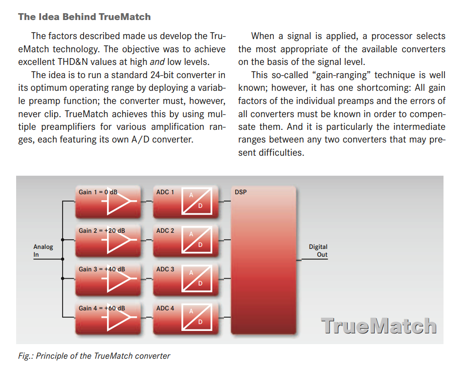
We can imagine the DSP outputting 32bit float audio, regardless of what happened before that. It's not really necessary, and in fact the TrueMatch devices don't output float, while others with a similar design (like Zoom and Sound Devices) do. But that's mainly a difference of UX.
More importantly, I think the big dynamic ranges of these multi-ADC devices (130+dB) should be taken with a grain of salt. Because the effective signal-to-noise ratio of a recording is still limited to that of any individual ADC. The standard dynamic range test with a -60dB tone doesn't expose this (unless the gain difference between ADCs is greater than 60dB), but some modified DR/SNR test might work. I hope this is taken into account for future measurements.
Last edited:
Hi BeerBear, if you'll excuse another one of my rants--not directed at you! It's misleading schematics like that which make understanding electronics difficult. It reads "when a signal is applied". As I've pounded my keyboard before, there's no "signal" coming through the wire, only a voltage. Because the "signal", the variations of voltage that lead to recognizable sound, is all we care about, we almost never talk about the voltage. FURTHER, because we mostly think in digital terms, where the signal can easily be preserved through almost limitless RE-AMPLIFICATIONS, it's easy to accept, based on that schematic, that the signal can be split up 4 times and sent to separate pre-amps, then ADCs.regarding gain-ranging, this is from an older ASR thread
I ask, why couldn't they have done what the schematic indicates with tubes? What new analog voltage splitter do we have that makes it possible now, and not then? Or even pre IC electronics? Exactly what electronics are at the node point between the analog in on the left, and the 4 nodes to the right?
Why is it forgotten that the "signal" in that "analog in" voltage is drowning in a sea of noisy electrons.
My 2-cents is there is a chipset that Zoom and Sound Devices is using where the gain is set to 0, then that pre-amped voltage regained to +20db, -+0d and each sent to an ADC. Even by their own bs logic, that schematic is false. I believe the accuracy of the ADCs, in this scenario, is not as good as the best single pre-amp/ADC combination.
Anyway, the ADCs then feed the DSP as shown above, but the REAL MAGIC happens as the DSP analyzed the 4 signals (digital data) and writes it out, as 24-bit fixed or 32-bit float, doesn't make a difference. The 32-bit float being new for these chipsets the end-use companies have used them to explain the better quality.
Photography is more my thing so let me compare. The RAW (internal) image from my state-of-the-art Samsung looks like a pixelated mess next to my full-frame Sony A7R3. HOWEVER, the image processing of the Samsung will create an image that looks like it came from a full-frame camera. Even I can be fooled. I never see the pixelated mess. Just as many people don't see the noisy data from the above quad ADC bs. So what camera do I use? If it's a nice day, plenty of light, my S22. (but if size weight no concern I would ALWAYS use my A7R3)
What about a low-lit day? That's where anyone can start noticing a difference. That's what I would expect from these new Zoom devices. With a good voltage from the mics they'll do great! The DSPs get better and better. But in situations where they can't get a good voltage they will end up with distortion (pixelation). It won't be blaringly obvious, but it will be noticed.
For high end work, just like photography, get the most noise free / clipping free voltages, the most accurate digitizing, and if you HAVE TO fix things up do the same thing the DSP would do, except with the state of art CPU/GPU and software in your computer.
Last edited:
The signal could be voltage, current, magnetic field, power, pressure, temperature, photons...
That schematic is a stereotypical multi-gain or floating-point ADC architecture. With separate ADCs, no switching is required, making life much easier. The DSP simply looks at the output from each ADC and chooses the one that is closest to full-scale without going over (clipping). That ADC's bits become the mantissa, and the gain becomes the exponent, in the floating-point output. The DSP can be pretty simple in that case (my version, many years ago, simply looked at a few bits from each ADC to decide which to choose and the "DSP" was a handful of gates on the chip).
If there is a buffer before the analog input in the schematic, then it's noise and distortion will add (in an RSS fashion) to the overall system. The selected gain stage will amplify the signal and the noise, ideally not changing the SNR, plus add some of it's own (which will).
This keeps going in circles.
Similar threads
- Replies
- 14
- Views
- 1K
- Replies
- 4
- Views
- 316
- Replies
- 2
- Views
- 428
- Replies
- 8
- Views
- 829