• WANTED: Happy members who like to discuss audio and other topics related to our interest. Desire to learn and share knowledge of science required. There are many reviews of audio hardware and expert members to help answer your questions. Click here to have your audio equipment measured for free!

Quick measurements of Pass Aleph 1.2 monoblock amplifier

pkane

Master Contributor
Forum Donor
Joined
Aug 18, 2017
Messages
5,707
Likes
10,396
Location
North-East
My personal amplifier/space heater/weight-training device is the Nelson Pass' Aleph 1.2 monoblock. I've had this pair since mid-nineties, and while I also have other amps on hand, this one has been the primary one dedicated to music listening (although it also served double-duty in the home theater for a while). Given the reputation and published measurements (by Stereophile) I was not expecting it to measure well compared to modern amps, and it didn't disappoint :)

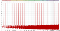
All measurements (unless otherwise stated) were done using REW at 5W output into 8Ω load, recorded by Cosmos ADC. Balanced (XLR) input was used.

The 60Hz line frequency and harmonics may be due a ground loop, but I was unable to resolve it by connecting/disconnecting grounds, using/not using separate power supplies (power plant), USB isolators, and running the laptop from a battery. Any suggestions on what else I can try are welcome. I'll update this post if I find a way to reduce it.

1 kHz tone:

1642447408192.png


Frequency response
freq.png


SMPTE 60Hz + 7kHz 4:1
1642445876408.png


CCIF 19k + 20k
CCIF19+20.png


Multitone
1642446163063.png


THD+N vs Frequency sweep @ 5W:
thd+freq.png


THD+N vs Power @1kHz:
power.png
 
Last edited:

restorer-john

Grand Contributor
Joined
Mar 1, 2018
Messages
12,728
Likes
38,935
Location
Gold Coast, Queensland, Australia
@pkane Would you mind showing a loopback multitone without the Aleph as a comparison/baseline?
 

Blumlein 88

Grand Contributor
Forum Donor
Joined
Feb 23, 2016
Messages
20,771
Likes
37,636
I had one of the Pass Aleph 0's for a time. It sounded nice, but sure did get hot. The multi-tone does look unusually clean. Did the 1.2 Aleph use no global feedback and as I recall like the 0 it was a single ended mosfet design?
 
OP
pkane

pkane

Master Contributor
Forum Donor
Joined
Aug 18, 2017
Messages
5,707
Likes
10,396
Location
North-East
I had one of the Pass Aleph 0's for a time. It sounded nice, but sure did get hot. The multi-tone does look unusually clean. Did the 1.2 Aleph use no global feedback and as I recall like the 0 it was a single ended mosfet design?

The really clean multitone is without the amp in the loop, per John’s request. That’s the Spring DAC playing into Cosmos ADC.

I don’t recall about global negative feedback, but likely minimal. Aleph 1.2 was a scaled up version of the smaller Aleph series amps. I had Aleph 5 before it and loved it, but it did clip on some tracks with my inefficient and hard to drive Thiel speakers. From specs (and from my measurements) 1.2 reaches 200W into 8 Ohms with under 1% THD and can drive max current into a short at the output all day long according to Pass ;)
 
Last edited:

pma

Major Contributor
Joined
Feb 23, 2019
Messages
4,608
Likes
10,779
Location
Prague
The 60Hz line frequency and harmonics may be due a ground loop, but I was unable to resolve it by connecting/disconnecting grounds, using/not using separate power supplies (power plant), USB isolators, and running the laptop from a battery. Any suggestions on what else I can try are welcome. I'll update this post if I find a way to reduce it.
You might try DAC only measurement, no loop, amp input shorted. Input COM of the balanced input ADC must be used then to avoid CMV error. Please use calibrated Y axis, in dBV.

To check if the loop in a full AD/DA setup is catching mains noise, just connect the two measuring input wires, shorted, onto the amplifier speaker cold output terminal. I guess it is not a bridged amp with 2 live output terminals. This would be the 2nd test to check your setup. This measurement should show clean measuring noise background. Anything else is a loop error.
 
Last edited:

garbulky

Major Contributor
Joined
Feb 14, 2018
Messages
1,510
Likes
829
The really clean multitone is without the amp in the loop, per John’s request. That’s the Spring DAC playing into Cosmos ADC.

I don’t recall about global negative feedback, but likely minimal. Aleph 1.2 was a scaled up version of the smaller Aleph series amps. I had Aleph 5 before it and loved it, but it did clip on some tracks with my inefficient and hard to drive Thiel speakers. From specs (and from my measurements) 1.2 reaches 200W into 8 Ohms with under 1% THD and can drive max current into a short at the output all day long according to Pass ;)
Which thiel?
 

pma

Major Contributor
Joined
Feb 23, 2019
Messages
4,608
Likes
10,779
Location
Prague
After playing with it some more, connecting the ADC ground to Aleph ground helped lower the noise floor just a little. Disconnecting DAC from the amp, lowered the 60Hz component, so it does seem to be a ground loop of some sort:

Paul, it should have been much better. I understand it is not trivial to get proper understanding of leakage currents and their influence on measurements. However they degrade the measurement and give bad image of the DUT.

My setup to measure amplifiers looks like this (input shorted wiring shown is used to measure system residual error from mains interference)

Amp_test_residual_noise_sch.png


And the residual noise error as per image above is

Amp_test_residual_noise.png

This is for the highest voltage sensitivity, max. input is 2V. Balanced input dividers are used to accommodate higher input level. The noise bottom remains flat.

You must not have any kind of analog gnd measuring loop.
 
OP
pkane

pkane

Master Contributor
Forum Donor
Joined
Aug 18, 2017
Messages
5,707
Likes
10,396
Location
North-East
Paul, it should have been much better. I understand it is not trivial to get proper understanding of leakage currents and their influence on measurements. However they degrade the measurement and give bad image of the DUT.

My setup to measure amplifiers looks like this (input shorted wiring shown is used to measure system residual error from mains interference)

View attachment 179742

And the residual noise error as per image above is

View attachment 179744
This is for the highest voltage sensitivity, max. input is 2V. Balanced input dividers are used to accommodate higher input level.

You must not have any kind of analog gnd measuring loop.

Thanks, Pavel, but I'm not sure what I can do to eliminate the ground loop for distortion measurements, since I do need the DAC and ADC in the loop and can't short them. When I was measuring PA-5, it had similar issues initially, until I connected amp and ADC grounds. I started with this:

unknown.png


And ended with this, with nothing shorted:
unknown.png
 
OP
pkane

pkane

Master Contributor
Forum Donor
Joined
Aug 18, 2017
Messages
5,707
Likes
10,396
Location
North-East
Paul, it should have been much better. I understand it is not trivial to get proper understanding of leakage currents and their influence on measurements. However they degrade the measurement and give bad image of the DUT.

My setup to measure amplifiers looks like this (input shorted wiring shown is used to measure system residual error from mains interference)

View attachment 179742

And the residual noise error as per image above is

View attachment 179744
This is for the highest voltage sensitivity, max. input is 2V. Balanced input dividers are used to accommodate higher input level. The noise bottom remains flat.

You must not have any kind of analog gnd measuring loop.

Pavel, here's the noise residual for Pass Aleph 1.2, shorting ADC input to negative speaker terminal, 8 ohm load:

1642464396938.png


1642464578480.png
 
  • Like
Reactions: pma

charleski

Major Contributor
Joined
Dec 15, 2019
Messages
1,098
Likes
2,240
Location
Manchester UK
One of Nelson Pass's theories is that distortion with 'negative phase' is euphonic. It might be interesting to see if this was implemented in this old design. REW's RTA can report on the phase of the distortion components, though frankly I'm not entirely sure how that correlates with the definition of negative and positive phase that pass provides.
 
OP
pkane

pkane

Master Contributor
Forum Donor
Joined
Aug 18, 2017
Messages
5,707
Likes
10,396
Location
North-East
One of Nelson Pass's theories is that distortion with 'negative phase' is euphonic. It might be interesting to see if this was implemented in this old design. REW's RTA can report on the phase of the distortion components, though frankly I'm not entirely sure how that correlates with the definition of negative and positive phase that pass provides.

Yeah, don't know what "negative phase" would be. 180 degrees? If so, it's nearly there with Pass Aleph at 1kHz @ -148deg:

1642465792289.png


Interestingly, the phase keeps getting closer to 180deg as frequency of the fundamental increases to about 5kHz:

1642466358600.png
 
Last edited:

charleski

Major Contributor
Joined
Dec 15, 2019
Messages
1,098
Likes
2,240
Location
Manchester UK
Yeah, don't know what "negative phase" would be.
I decided to model this by mixing together 500Hz and 1kHz (reduced by 40dB) signals in Audition. If I arrange the two waves so that the positive and negative peaks of the 500Hz signal align with the negative peak of the 1kHz that seems to match his description of 'negative phase':
NegativePhase.PNG


Feeding this into REW's RTA gives a 2nd harmonic distortion phase of 82 degrees (I probably didn't match the peaks perfectly). Doing the same but with the 500Hz peaks aligned with the positive peak of the 1kHz signal gives a distortion phase of -90 degrees.

If I align the waves so that the down->up zero-crossing of the 1kHz signal aligns with the peaks of the 500Hz signal like so:
Peak-DownUp.PNG

then I get a distortion phase of 173 degrees (a less than perfect alignment again), similar to your result here. Aligning the peaks of the fundamental with the up->down zero crossing gives a distortion phase of 0 degrees.

Of course, the little diagrams he uses to define the term shows waveforms whose alignment falls somewhere in between these two options, but it does seem closer to my initial guess with the coincident peaks. So maybe he hadn't come up with the 'negative phase' idea when he designed this amp or the distortion phase changes significantly across the spectrum (perhaps more likely given the 33 degree change you saw from 1 to 5kHz).
 

tvrgeek

Major Contributor
Joined
Aug 8, 2020
Messages
1,017
Likes
566
Location
North Carolinia
I suggest the 60 Hz may be old main bank caps. Big old cans life span is not that long. Just re-did my old amp. Audible hum to just detectable at the noise floor. Can't hear a thing at the speaker or feel with my finger. It is only a 60W amp and I used 4 x 6800 on each rail, so not excessive.
 

tvrgeek

Major Contributor
Joined
Aug 8, 2020
Messages
1,017
Likes
566
Location
North Carolinia
I decided to model this by mixing together 500Hz and 1kHz (reduced by 40dB) signals in Audition. If I arrange the two waves so that the positive and negative peaks of the 500Hz signal align with the negative peak of the 1kHz that seems to match his description of 'negative phase':
View attachment 179914

Feeding this into REW's RTA gives a 2nd harmonic distortion phase of 82 degrees (I probably didn't match the peaks perfectly). Doing the same but with the 500Hz peaks aligned with the positive peak of the 1kHz signal gives a distortion phase of -90 degrees.

If I align the waves so that the down->up zero-crossing of the 1kHz signal aligns with the peaks of the 500Hz signal like so:
View attachment 179919
then I get a distortion phase of 173 degrees (a less than perfect alignment again), similar to your result here. Aligning the peaks of the fundamental with the up->down zero crossing gives a distortion phase of 0 degrees.

Of course, the little diagrams he uses to define the term shows waveforms whose alignment falls somewhere in between these two options, but it does seem closer to my initial guess with the coincident peaks. So maybe he hadn't come up with the 'negative phase' idea when he designed this amp or the distortion phase changes significantly across the spectrum (perhaps more likely given the 33 degree change you saw from 1 to 5kHz).
I found the differences in the general "slope" of distortion between Dominant Pole and Miller compensation to be the audible difference between two modified Rotel amps. As regaining the same level of stability required other small changes that effected the speed, they may also effect the phase of both fundamentals and harmonics.

Is there a reference where Mr. Pass talks about this?
 

restorer-john

Grand Contributor
Joined
Mar 1, 2018
Messages
12,728
Likes
38,935
Location
Gold Coast, Queensland, Australia
@pkane

Do you know what this is? ~16.5kHz?

1642505433753.png


I get one at 16kHz here. Is it a USB packet 'harmonic' or something?
 
Top Bottom