somebodyelse
Master Contributor
- Joined
- Dec 5, 2018
- Messages
- 5,320
- Likes
- 4,906
I'd look at that, and U002 in the block above that one.
I'd look at that, and U002 in the block above that one.
There's more to it than that.
Yes, good catch together with @somebodyelse . I do think however that these might be cascaded behind one of the 2 DC/DCs. Hard to see from the pics.There's more to it than that.
The top one is a voltage regulator or transistor for it, the two SOIC8s are probably high frequency regulators.
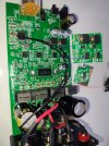
I also know the very basics… maybe a tad more: enough to become literally dangerous!I know only the very basics on circuitry, how can I identify the voltage regulator(s)? Are they they chips in between the large capacitors in my <teardown pics>?

There's more to it than that.
The top one is a voltage regulator or transistor for it, the two SOIC8s are probably high frequency regulators.
Can you take photos of the components where you can read the labels?
View attachment 406070
There's more to it than that.
The top one is a voltage regulator or transistor for it, the two SOIC8s are probably high frequency regulators.
Can you take photos of the components where you can read the labels?
View attachment 406070
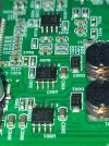
This is probably the important one. It can input up to 80V, so it's super wide-range input. Very useful, but not very common.XL7005A (DC/DC converters?)
Those are marked "SS16F" 60V Schottky Diodes ?I also know the very basics… maybe a tad more: enough to become literally dangerous!
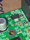
As @Roland68 indicated, the components markings and, in my experience, Googling them around, are a good indication of what you’re dealing with.
Same with the markings on the PCB: for example on your initial picture,
View attachment 406081
These 4 components are referenced D3, D4, D5, D6 on the PCB. I can’t read the actual marking on the components, but I bet these are the 4 diodes (as “Dx”) of the bridge rectifier, not the voltage regulator…
Now, to figure out how all of these components fit together and what is their likely function… You need the experts!
Based on this limited info, probably yes. The diodes are there to limit voltage to 60V. So that should be the real-world limit.I have no idea about how to do this, but... reguardless you think I can use a 32V if not 36V supply safely?
There's more to it than that.
The top one is a voltage regulator or transistor for it, the two SOIC8s are probably high frequency regulators.
Can you take photos of the components where you can read the labels?
View attachment 406070
so it might be possible that it’s the same board with slightly different BOM.well if ChatGPT said it, it must be trueChatGPT seems to think that it is possible to make a board that can accommodate both chips
That doesn't make sense. The coordination alone to save costs in production would be far too complex. There isn't much to save there either.The TPA3244 board looks exactly the same as the TPA3255 board, I mean the power supply parts.
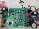
I wonder if they used all the same parts and just used a couple different resistores to change the LM317G regulator's output?
That would save mfg costs I think. Make any sense that they would do this?
(see the TPA3255 board pic below with the same LM317G and looks like exact same layout)
On the other hand, why would you re-design a board if you don't have to? It's obvious how similar the requirements are.That doesn't make sense. The coordination alone to save costs in production would be far too complex. There isn't much to save there either.
LM317/337 voltage regulators are absolutely mass-produced and the most commonly used regulators after 78/79XX, not just in the audio sector.
I wasn't referring to the circuit board, but it doesn't really matter whether the circuit board is the same or different.On the other hand, why would you re-design a board if you don't have to? It's obvious how similar the requirements are.
I think there'd be more coordination/management needed the more parts you have to source and keep in stock.
Point is, it's obvious these two amps are nearly the identical save for the TPA chips.
Why have two then, why not just have the 3255 higher power amp?... maybe they sound different?... don't think anyone has A-B them.
On the other hand, why would you re-design a board if you don't have to? It's obvious how similar the requirements are.
I think there'd be more coordination/management needed the more parts you have to source and keep in stock.
Point is, it's obvious these two amps are nearly the identical save for the TPA chips.
Why have two then, why not just have the 3255 higher power amp?... maybe they sound different?... don't think anyone has A-B them.
I have to apologize to both of you, it seems to be a board for TPA3244 and 3255.The main reason to create a single board for two products would be to lower NRE and possibly certification costs.