For this filter, I simply construct the frequency (and phase) response I want in the frequency domain, and then ifft it. The null will persist regardless of slope, because 0 is in between 1 (which is what you want at low frequencies) and -1 (which is what you want at high frequencies). I can control the character of the transition, within reason. Very abrupt changes in response require a lot of taps. On the other hand, if we spread the transition across a lot of frequency, there's a lot of bandwidth where the drivers aren't contributing how we want them to. Perhaps for simulation purposes it is good to widen the transition, to get a really good feel for how it performs in the transition region. We could narrow it up later. Do you know what sample rate you will want to run at? Also, do you agree that 150 Hz is a good transition frequency, or would you like to move it?That's pretty cool. It's a very sharp filter though, so not sure if that is what is needed. How did you construct it? A slowly changing filter should also get rid of the null I guess.
I think it can do something like 2k taps in total, so on 4 channels, that would be like 500. But possibly you can share some channels, so if one is a bit smart, you can do a bit more. But even with 500, I guess one can do some interesting things.
I do need to switch simulation software for this, I don't think BoxSim can do convolution. I'll double check.
-
Welcome to ASR. There are many reviews of audio hardware and expert members to help answer your questions. Click here to have your audio equipment measured for free!
You are using an out of date browser. It may not display this or other websites correctly.
You should upgrade or use an alternative browser.
You should upgrade or use an alternative browser.
On paper experiment of a Bessel line array
- Thread starter voodooless
- Start date
- Thread Starter
- #22
If you see it as level, then yes. if you see it as pure phase, then no, there should not be a null.For this filter, I simply construct the frequency (and phase) response I want in the frequency domain, and then ifft it. The null will persist regardless of slope, because 0 is in between 1 (which is what you want at low frequencies) and -1 (which is what you want at high frequencies).
I have no idea what the proper frequency would be. Possibly the outer driver might need a lower frequency than the inner one... This needs some experimenting.I can control the character of the transition, within reason. Very abrupt changes in response require a lot of taps. On the other hand, if we spread the transition across a lot of frequency, there's a lot of bandwidth where the drivers aren't contributing how we want them to. Perhaps for simulation purposes it is good to widen the transition, to get a really good feel for how it performs in the transition region. We could narrow it up later. Do you know what sample rate you will want to run at? Also, do you agree that 150 Hz is a good transition frequency, or would you like to move it?
I could transition using a phase rotation as well, but I figured that's close to what you did with passive, which you already indicated didn't work out. I'm happy to make both, though, if you can test them.If you see it as level, then yes. if you see it as pure phase, then no, there should not be a null.
I have no idea what the proper frequency would be. Possibly the outer driver might need a lower frequency than the inner one... This needs some experimenting.
It would seem to me that it's simpler to have all the negated drivers in the bessel array transition to positive the same way, to reduce the required number of DSP and amplification channels. But it's also good to investigate the optimum way of doing it, and then choose to compromise later.
Does your DSP operate at 48 kHz, or 96 kHz, or something else?
This thread sparked my interest in Bessel arrays. In particular, I wanted to see if a good LCR could be made, with similar dispersion characteristics whether placed horizontally or vertically. Most speakers that are long in one dimension don't work well when that dimension is horizontal. I figured bessel arrays had the best chance at mitigating that issue, and if I could revert the phase of the negative channels at low frequencies, they could offer efficiency where it's needed most.
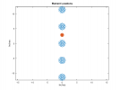
So first I wanted to check the basics. I simulated a 5 element bessel array as point sources, and put the listening position in the (very) far field. This produced a nice uniform response with only minor ripple.
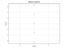
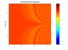
Next I brought the listening position into something reasonable. In this case, it's 11 feet. Now there was some inconsistency at the higher frequencies. Bessel arrays work perfectly well when the phase delays are equal across the array, but imperfectly in closer proximity.
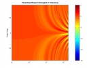
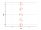
Next I modeled each driver as numerous point sources (ignoring the depth profile of the cone). This still provides directivity (beaming) to the drivers at higher frequencies that can be pretty realistic. It's clear to see that the dispersion at high frequencies is lacking.
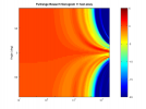
So first I wanted to check the basics. I simulated a 5 element bessel array as point sources, and put the listening position in the (very) far field. This produced a nice uniform response with only minor ripple.


Next I brought the listening position into something reasonable. In this case, it's 11 feet. Now there was some inconsistency at the higher frequencies. Bessel arrays work perfectly well when the phase delays are equal across the array, but imperfectly in closer proximity.

Next I modeled each driver as numerous point sources (ignoring the depth profile of the cone). This still provides directivity (beaming) to the drivers at higher frequencies that can be pretty realistic. It's clear to see that the dispersion at high frequencies is lacking.


I wanted to even out the dispersion by adding a tweeter. I utilized a 4th order acoustic slope crossover at 2 kHz. I figured this would be easy and effective. It seemed natural to utilize the 7 element bessel arrays that use 6 drivers and have a hole in the middle: a great place to put a tweeter.
I figured out from simulation that it was advantageous to put the tweeter closer to the side of the array that was all positive. I grew the array to allow a significant off-center placement of the tweeter. This still yielded some interference issues at the crossover frequency.
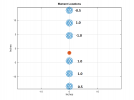
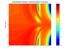
I tried trying to keep the array short and compact, even though this only allowed for a minimal tweeter offset. This time the interference issues are a bit different, and more symmetrical, but still present.
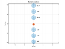
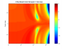
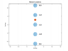
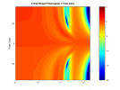
I checked to see if the 5 element bessel would behave better. I had to separate the drivers a bit to make room for the tweeter. In this case, I found I had to put the tweeter between the 2 positive, full power drivers. This yields a fairly wide range of angles that are neutral, but there would still be a major spike in the directivity. Still, this may be the best option I've simulated.
One of the nice things about the 5 element bessel is the potential to get a reasonable impedance by utilizing 16 ohm drivers. Adding that 6th driver in parallel for the 7 element bessel would drive impedance to an uncomfortably low level.
I think voodooless made a good choice with the 16 ohm faitalpro. As a bessel array, I estimate the sensitivity would be somewhere around 94 dB, which is why I had the SB Acoustics SB29RDNC-C000-4 in mind when I ran my sims. It has a small faceplate and high sensitivity, and can be crossed pretty low. If one were willing to accept a higher crossover frequency, there are a lot more options (including cheaper options).
I'm not sure where to go from here. I figured I'd post and start a discussion and perhaps a solution would reveal itself.
I did try a bessel array of tweeters, but the imperfections of the bessel array at reasonable in-home listening distances revealed itself again.
I figured out from simulation that it was advantageous to put the tweeter closer to the side of the array that was all positive. I grew the array to allow a significant off-center placement of the tweeter. This still yielded some interference issues at the crossover frequency.


I tried trying to keep the array short and compact, even though this only allowed for a minimal tweeter offset. This time the interference issues are a bit different, and more symmetrical, but still present.


I checked to see if the 5 element bessel would behave better. I had to separate the drivers a bit to make room for the tweeter. In this case, I found I had to put the tweeter between the 2 positive, full power drivers. This yields a fairly wide range of angles that are neutral, but there would still be a major spike in the directivity. Still, this may be the best option I've simulated.


One of the nice things about the 5 element bessel is the potential to get a reasonable impedance by utilizing 16 ohm drivers. Adding that 6th driver in parallel for the 7 element bessel would drive impedance to an uncomfortably low level.
I think voodooless made a good choice with the 16 ohm faitalpro. As a bessel array, I estimate the sensitivity would be somewhere around 94 dB, which is why I had the SB Acoustics SB29RDNC-C000-4 in mind when I ran my sims. It has a small faceplate and high sensitivity, and can be crossed pretty low. If one were willing to accept a higher crossover frequency, there are a lot more options (including cheaper options).
I'm not sure where to go from here. I figured I'd post and start a discussion and perhaps a solution would reveal itself.
I did try a bessel array of tweeters, but the imperfections of the bessel array at reasonable in-home listening distances revealed itself again.
Nice find of the tweeter placed between two positive woofer. I am interested why the tweeter can't use bessel array, I thought for the size of tweeter the listening position and array length ratio will be higher.I did try a bessel array of tweeters, but the imperfections of the bessel array at reasonable in-home listening distances revealed itself again.
- Thread Starter
- #27
I suspect that the single tweeter has to much interference with the woofers further away. There might be some things that could be done here:Nice find of the tweeter placed between two positive woofer. I am interested why the tweeter can't use bessel array, I thought for the size of tweeter the listening position and array length ratio will be higher.
- very steep filters, so interference is minimal
- different filters for different woofers, so we can more gradually filter stuff out depending on the distance.
In array processing there is the concept of an "acoustic center" to the array. Typically if every element is in-phase (even if magnitudes are different), you can take the weighted average of the element locations and calculate the acoustic center. With Bessel arrays there are elements that are 180 degrees out of phase with the rest. The result is an interference pattern between them, but one that has been specifically designed to maintain approximately constant magnitude across angle (actually across wave-number space, but close enough). If we filter the elements differently at high frequencies, the response will no longer be consistent across angle.
As I see it, the issue with crossing over to a tweeter is that the Bessel array doesn't actually have a consistent acoustic center. Because of the interference between the drivers, the acoustic center shifts as you move off axis. To simplify this, you could consider that at different angles, the out-of-phase elements cancel different combinations of the in-phase elements.
For what it's worth, I did try an odd-order crossover, but that resulted in a response that was good on one side, bad on the other.
I'm still waiting for a good solution to present itself.
It's possible, but there will still be some issues. You could squeeze your tweeters in between your fullrange drivers, but that still results in an offset between the 2 arrays. Sort of like this OoOoOoOoOo (but colinear). That geometry still has dispersion problems at the crossover. Also, review post 24 to see the issues associated with a bessel array that has several inches between drivers when they are producing wavelengths much smaller, and you are at a typical listening distance. The homogenous response begins to break down.Is it possible to also put 5 tweeters too to make the tweeter also a bessel array along the woofers? But this way will add more driver cost, probably not an elegant solution.
You could make two parallel lines more like this 88888. You'll be able to squeeze your mids closer together, which will increase the frequency to which they can maintain homogenous response, but will still have issues in the upper treble at typical listening distances. Also, if you try to use it vertically as a left and right, you've created a dispersion issue in the horizontal direction.
If you used a small coaxial driver you would eliminate the issue of the vertical array having problems with horizontal dispersion, but would still have the issue of the homogenous dispersion breaking down in the upper treble region. Maybe that's not as problematic as it appears. I know people run full-range line arrays with comb filtering at higher frequencies and still like them.
So I simulated a bessel array of 5 tweeters next to a bessel array of 5 full-range drivers. I made the tweeter array 1/2 the length of the woofer array. This appears to do a good job of keeping fairly uniform response along the long axis of the array. Unfortunately, with 2 offset arrays, it created the predictable issue in the horizontal plane.
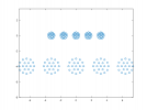
However, it looks to me like we have a good solution for a vertical bessel array, with the single tweeter stuck in between the postitive full-range drivers. We also have a good solution for a center channel bessel array, with a shortened array of tweeters above the full-range array.
It's unfortunate that the approaches would have to be different, but it actually looks like a reasonable solution. I have chores and halloween prep to get to, but I think if you're willing to build a different speaker for center vs left and right, you could use bessel arrays for all three.
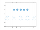
Center would have a geometry like this:
Left and right like this:
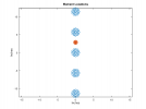
However, it looks to me like we have a good solution for a vertical bessel array, with the single tweeter stuck in between the postitive full-range drivers. We also have a good solution for a center channel bessel array, with a shortened array of tweeters above the full-range array.
It's unfortunate that the approaches would have to be different, but it actually looks like a reasonable solution. I have chores and halloween prep to get to, but I think if you're willing to build a different speaker for center vs left and right, you could use bessel arrays for all three.
Center would have a geometry like this:

Left and right like this:

Last edited:
If there was a tweeter with a small faceplate, a 16 ohm impedance, and enough sensitivity to keep up with the faitalpro, you could build the double-bessel array with a passive crossover and use 1 amplifier channel. Does anyone know of such a tweeter? I'm thinking it doesn't exist.
I did find this interesting patent for an improved bessel array.
 www.freepatentsonline.com
This site also has an interesting dual bessel array center channel with woofers on the sides as well:
I am curious how they solved the impedance issue with the tweeters.
I did find this interesting patent for an improved bessel array.
Bessel array
Complete Patent Searching Database and Patent Data Analytics Services.
This site also has an interesting dual bessel array center channel with woofers on the sides as well:
cc-3wc
www.sourcespeaker.com
I am curious how they solved the impedance issue with the tweeters.
Last edited:
Are they selling the speaker? I thought there is patent on bessel array, maybe they licensed it?This site also has an interesting dual bessel array center channel with woofers on the sides as well:
cc-3wc
I am curious how they solved the impedance issue with the tweeters.
Nice work! Do you have simulations for those? Thank you.
- Thread Starter
- #34
I actually tried several of the more practical setups but found them mostly not really improving stuff if you look at the details. I think more complex active filtering can actually bring better improvements. Still didn't find time to make some sims..If there was a tweeter with a small faceplate, a 16 ohm impedance, and enough sensitivity to keep up with the faitalpro, you could build the double-bessel array with a passive crossover and use 1 amplifier channel. Does anyone know of such a tweeter? I'm thinking it doesn't exist.
I did find this interesting patent for an improved bessel array.
Bessel array
Complete Patent Searching Database and Patent Data Analytics Services.www.freepatentsonline.com
Wow, that's a big boy!This site also has an interesting dual bessel array center channel with woofers on the sides as well:
cc-3wc
www.sourcespeaker.com
I am curious how they solved the impedance issue with the tweeters.
- Thread Starter
- #35
So, a new idea: what about using BMR drivers? They have an excellent off-axis response, so there would not be a need for a tweeter. Distortion of those things is also quite good. They also have quite some excursion, so might go loud enough. The BMR TEBM46C20N-4B is about 30 euros a pop and also quite efficient 86 dB. It will need some help in the bass department though. But it looks like they might go > 110 dB > 300 Hz given some filtering magic.
- Thread Starter
- #36
It should look something like this:

Woofers might be Faital 5FE120. This should still get loud enough > 60Hz. The unit would be about 70cm in width, about 15 cm in height. Will try to do some sims later this week.
Woofers might be Faital 5FE120. This should still get loud enough > 60Hz. The unit would be about 70cm in width, about 15 cm in height. Will try to do some sims later this week.
The datasheet for the BMR fullrange is kind of misleading. It has 1/3 octave smoothing, and hides a hole in the treble response. If you look at the measurements from hificompass, you'll see the hole at about 10 kHz.
 hificompass.com
It's a 4 ohm load so it would be difficult to use passively (unless there's a wiring topology that works that I haven't considered), but if you're using multiple amps you should be able to make it work. If you're crossing to woofers anyway, I'm not sure you'll need the transition to a more typical line array at low frequencies (with everything firing in phase at full power).
Tectonic TEBM46C20N-4B | HiFiCompass
The THD measurements at distance of 315 mm and voltage level 2.83 Volt were carried out with High Pass Filter "on" (2nd order Buttreworth type, 100 Hz cutoff, HPF2-100) The THD measurements at distance of 315 mm and voltage levels from 4 Volt to 5.6 Volt were carried out with High Pass Filter...
It's a 4 ohm load so it would be difficult to use passively (unless there's a wiring topology that works that I haven't considered), but if you're using multiple amps you should be able to make it work. If you're crossing to woofers anyway, I'm not sure you'll need the transition to a more typical line array at low frequencies (with everything firing in phase at full power).
thewas
Master Contributor
- Joined
- Jan 15, 2020
- Messages
- 8,207
- Likes
- 22,998
Yes, I have also experimented with them and due to that hole and also higher beaming in the last octave I would recommend combining them with a (super)tweeter crossed around 8 kHz or lower.The datasheet for the BMR fullrange is kind of misleading. It has 1/3 octave smoothing, and hides a hole in the treble response. If you look at the measurements from hificompass, you'll see the hole at about 10 kHz.
- Thread Starter
- #39
Thanks, that is good data. I've seen the hole as well on other units, was wondering why this one didn't have it. Really not that much of an issue, since we can partially EQ it away, and the array will average things a bit out as well.The datasheet for the BMR fullrange is kind of misleading. It has 1/3 octave smoothing, and hides a hole in the treble response. If you look at the measurements from hificompass, you'll see the hole at about 10 kHz.
Tectonic TEBM46C20N-4B | HiFiCompass
The THD measurements at distance of 315 mm and voltage level 2.83 Volt were carried out with High Pass Filter "on" (2nd order Buttreworth type, 100 Hz cutoff, HPF2-100) The THD measurements at distance of 315 mm and voltage levels from 4 Volt to 5.6 Volt were carried out with High Pass Filter...hificompass.com
I'll go active anyway, so don't see a real issue there.It's a 4 ohm load so it would be difficult to use passively (unless there's a wiring topology that works that I haven't considered), but if you're using multiple amps you should be able to make it work. If you're crossing to woofers anyway, I'm not sure you'll need the transition to a more typically line array at low frequencies (with everything firing in phase at full power).
Well, the point was to not use a tweeterYes, I have also experimented with them and due to that hole and also higher beaming in the last octave I would recommend combining them with a (super)tweeter crossed around 8 kHz or lower.
thewas
Master Contributor
- Joined
- Jan 15, 2020
- Messages
- 8,207
- Likes
- 22,998
Yes, we also had planned to make a small array with them but it didn't sound as homogeneous as I had wished, so we had added a tweeter. Nubert and Dennis also combine them with tweeters probably due to similar reasons.Well, the point was to not use a tweeterWe'll see what the simulations will tell us.
Similar threads
- Replies
- 5
- Views
- 842
- Replies
- 19
- Views
- 2K
- Replies
- 20
- Views
- 2K
- Replies
- 0
- Views
- 411

