• WANTED: Happy members who like to discuss audio and other topics related to our interest. Desire to learn and share knowledge of science required. There are many reviews of audio hardware and expert members to help answer your questions. Click here to have your audio equipment measured for free!

On paper experiment of a Bessel line array

voodooless

Grand Contributor
Forum Donor
Joined
Jun 16, 2020
Messages
10,393
Likes
18,340
Location
Netherlands
Instead of actually building a speaker, you can also have a lot of fun simulating one, and learning something along the way :cool:

In that spirit, I was contemplating the following scenario: I'd like to add some acoustic damping to my room, but I'd also want to have some wife friendly surround setup, that still performs halfway decent. So why not try to combine the two?

This is what I came up with: Why not build a shallow speaker panel that is actually mostly built out of acoustic absorption material, but also houses the speaker units. Covering the whole with a proper and nice-looking fabric will make it just look like just a panel, rather than a surround speaker. That way I could cover the rear and side surround channels, giving much-needed room damping especially to the wall behind the listeners. Furthermore, one could hide some speakers on the top side to act as Atmos height channels. But that's not the focus for today ;)

So a wall near the panel has some challenges, as well as some advantages. Firstly, because of the wall closeness, you get quite a boost in bass response, so little or no baffle step compensation is needed. Secondly, you get some massive size constraints. Only small or shallow build units will fit. So choices are rather limited.

Now I thought, how about a line array? You can use multiple smaller speakers to get decent output, and if we can hit 80 Hz, we should be more or less okay. Now I didn't want to break my virtual bank either, so the line has to be not very long. 5 units would be the maximum for this experiment.

Driver choice needs to be something cheap and decent, with enough high-frequency extension to not need a tweeter. My choice is the FaitalPro 4FE32:
1625839666204.png

They are about 20 euro's each if you buy 5, cheaper if you buy more ;) For that, you get a smooth driver with a neo motor and low distortion profile and resonance figures.

So let's line them up and see. For this I used Boxsim. It's a tool that has been around for quite a while and might be familiar to people using Visaton drivers since it comes with a full dataset of those drivers. I've used it several times before and it's quite okay, but a bit clunky. There are other options for sure, but I know how to use it, and I have it running without issues on my Mac (as opposed to some of the other free tools out there).

First up a normal 5-unit vertically aligned array. I offset the drivers on the panel (of roughly 50x50cm) to about 1/3 of the right side. This will improve the radiation pattern a bit in the sims, but in the real world, when the panel is against the wall, this should not matter. I use Engauge Digitizer (very klunky tool) to trace the frequency response and impedance plots from the datasheet and entered all the data in Boxsim.
1625840196722.png

Top image is horizontal coverage, bottom is vertical. Clearly the vertical has the typical narrowing of the line array. This can also clearly be seen in the directivity plot:
1625840411995.png

Now One major issue here is obviously that ceiling and floor reflections will be quite unpredictable. Sadly Boxsim can't simulate this. The good news is the power handling. Since the Faital driver already brings 2.5mm Xmax, is can take quite a beating. This configuration in bass-reflex should be fine for > 115 dB at 1m from around 100 Hz on.

But the vertical dispersion bugs me. Now I found some pages about a Bessel type of array. It shaded the drivers to a Bessel function, and that way improves vertical dispersion. There are several configurations possible, and even some improvements are possible on the original design. I however found that they mostly bring a bit more bass efficiency, and worse off-axis response, mostly in the midrange.

So I settled for the most simple setup with a 5 driver setup. shading is:

.5 -1 1 1 .5

So the outer woofers are at half power, the rest is full power, with one of the three inverted. So what does that look like:
1625841466071.png

Wow :eek:, now suddenly the vertical looks quite good as well. The downside is that we lost about 5 dB inefficiency. Consequently the polars looks quite nice:
1625841624011.png

1625841664565.png


Obviously, the max SPL is down by about 5dB as well, but it's still not bad. Also, I cheated a bit with the response: I added a few PEQ's to smooth it out a bit, which in reality I would have done anyway. Also note that I used the 8 Ohm version. This ends up with a quite low impedance, so is not very amp friedly. You could do the same with the 16 Ohm version as well, and that would give you a resonable impedance. Just did not have to time to redo the whole thing.

All in all, I think this is quiet an interesting option for such speaker, and I'm actually contemplating making them and see how good it really works :)
 

hex168

Senior Member
Joined
May 29, 2020
Messages
399
Likes
341
Very interesting. I've ignored Bessel arrays, somehow picking up the impression that they are only useful for large venues. Don't know where I got that idea from.

Looking at your sim, I'm wondering what would happen if the upper .5 driver were switched for a tweeter. Looks like something crossed over around 1500-1800 would solve the vertical issues occurring within +-15 degrees and improve the horizontal directivity plot. Is Boxsim able to simulate that setup?
 
OP
voodooless

voodooless

Grand Contributor
Forum Donor
Joined
Jun 16, 2020
Messages
10,393
Likes
18,340
Location
Netherlands
Very interesting. I've ignored Bessel arrays, somehow picking up the impression that they are only useful for large venues. Don't know where I got that idea from.

Looking at your sim, I'm wondering what would happen if the upper .5 driver were switched for a tweeter. Looks like something crossed over around 1500-1800 would solve the vertical issues occurring within +-15 degrees and improve the horizontal directivity plot. Is Boxsim able to simulate that setup?

I haven’t tried to replace the upper driver yet. I could give it a try. I did try a 7 driver array. Because the middle driver is non-functional in this setup, you could put something else in place. So I tied a tweeter and a simple 12 dB passive filter. Results were not very encouraging. Only replacing the upper one with a tweeter is not that easy. Normally you would do the upper and lower in series. With a tweeter, you can’t do that easily because it needs high pass filtering. That would also filter the lower driver unless some kind of series filter is employed, or you’ll need a different impedance for the lower driver and use a normal parallel filter.

I’ll give this another try with 3FE25 or SB65. It will have less beaming, at the expense of max-SPL. Another disadvantage of the 4” wideband is that it needs quite a bit of volume.. also mixing and matching drivers might be interesting. 5FE100 with 3FE25 for instance…but that adds a lot of complexity as well.
 

bigjacko

Addicted to Fun and Learning
Joined
Sep 18, 2019
Messages
722
Likes
360
Very interesting stuff, learned something today!
I use Engauge Digitizer (very klunky tool) to trace the frequency response and impedance plots from the datasheet
You can use web plot digitizer for this too.

The 5 driver horizontal direcitvity looks the same as no shading and the same as single driver except the SPL. Bessel array works great for vertical directivity, I can see they are not the same as horizontal but really really close. One thing I don't understand is why for single driver the vertical and horizontal directivity are close but not the same? Also how do you determine which one to be -1 shading?
 
OP
voodooless

voodooless

Grand Contributor
Forum Donor
Joined
Jun 16, 2020
Messages
10,393
Likes
18,340
Location
Netherlands
One thing I don't understand is why for single driver the vertical and horizontal directivity are close but not the same?

Because it’s not just the driver, but also the baffle. Sine the baffle is a rectangle and the center driver is offset, the axis are not exactly the same

Also how do you determine which one to be -1 shading?

Well, the basics are given bij the Bessel function. You can then choose for the second or fourth driver to make it -1. Looking at the plots, I don’t think it would matter that much.
 
OP
voodooless

voodooless

Grand Contributor
Forum Donor
Joined
Jun 16, 2020
Messages
10,393
Likes
18,340
Location
Netherlands
Did some tries with SB65, but it yields low efficiency and not a lot of MaxSPL, so it's not really an option. Models also did not show a lot of high-frequency improvement.

Also tried adding two 5" woofers with a 2nd order filter. That adds a bit of bottom end, but also more complexity.

So last thing I did is make the baffle much bigger to simulate how it would work on a large wall. That actually extends directivity to below 200 Hz and quite smooth as well. It also removed the need for a reflex box and extends bass down to about 70 Hz:
1626082670252.png


Since it looks like it might be actually worthwhile building this, the next steps will be:
- Move to 16 Ohm version to make impedance nice for amps
- Try to make some actual design drawings
- See how I can simulate some Atmos height channels to put on top
 

hex168

Senior Member
Joined
May 29, 2020
Messages
399
Likes
341
I haven’t tried to replace the upper driver yet. I could give it a try. I did try a 7 driver array. Because the middle driver is non-functional in this setup, you could put something else in place. So I tied a tweeter and a simple 12 dB passive filter. Results were not very encouraging. Only replacing the upper one with a tweeter is not that easy. Normally you would do the upper and lower in series. With a tweeter, you can’t do that easily because it needs high pass filtering. That would also filter the lower driver unless some kind of series filter is employed, or you’ll need a different impedance for the lower driver and use a normal parallel filter.

I’ll give this another try with 3FE25 or SB65. It will have less beaming, at the expense of max-SPL. Another disadvantage of the 4” wideband is that it needs quite a bit of volume.. also mixing and matching drivers might be interesting. 5FE100 with 3FE25 for instance…but that adds a lot of complexity as well.
I was thinking just a high pass and attenuation on the tweeter and for simplicity's sake (avoiding the series connection) just using a less sensitive driver for the other .5 driver. Maybe that is overly simplified? One would not gain the full benefit of the Bessel array below the xover frequency, but it gets less important for lower frequencies. It may be time for me to learn Boxsim. Thanks for the sim results and for bringing this topic up.
 
OP
voodooless

voodooless

Grand Contributor
Forum Donor
Joined
Jun 16, 2020
Messages
10,393
Likes
18,340
Location
Netherlands
So this was quite a fun experiment so far. Fun enough to possibly warrant a real implementation with some more room for experimentation :)

Initially, I talked about wall mounted surround speakers, but there is another obvious candidate as well: a centre speaker. Since I do not have a lot of room between floating TV and cabinet, A lower profile centre would actually be a good idea. And since a horizontal MTM would not be a good idea unless it would be a 2.5-way, a design with 5 wideband speakers might fit very well.

But there is some opportunity here for more! What if we were to power the thing with a 4 channel DSP and amplifier? That would mean the outer woofers would share a channel, and the rest would get their own. And there is a cheap way to get this: The Sure/Wondom JAB4 board. For € 55 we have 4 channels of 30W@8R and a DSP, and they even throw in Bluetooth! Missing is a power supply and a programmer for the DSP. Power bricks are easy and cheap, so no issues there. As for the programmer, they are not so hard to find, but most of them need USB and drivers, and since I use SigmaStudio on my Mac using crossover, that option doesn't really work. So I found an easy way to do it wirelessly using an ESP wifi board. It's even a cheaper solution :)

That leaves the drivers. Easiest would be to use 3x8 ohm and then use 2x16 Ohm versions in parallel for the outer drivers. That gives 4 times 8R on the amps.

The 4xDSP also gives several other neat options:
- We can make a normal Bessel filter arrangement as describes above. My guess would be that one can fine-tune the directivity by individually EQ'ing the channels. That would however mean I would actually be able to do good enough off-axis measurements in the first place ;)
- We can actually use it as a stereo soundbar with the following:
1634282232613.png

The pots actually let you choose the stereo width, so might be a fun effect for casual listening via Bluetooth.
- We can have a more normal 3-way/2.5-way setup in which the middle driver plays as tweeter, the outer drivers do bass, and the inner drivers do bass and or midrange.

The big question here is: will the cheap Sure board be "audiophile" enough. SINAD is definitely not impressive, but it's really not worse than what an amplifier in the impressive speaker like the Genelec 8050B uses. So if it works for Genelec, why not for me. I'm most worried about audible noise. But I figure worst case: I'd rip out the fun DSP, and replace it with something "better" ;)

The next steps:
1. Do some more simulations with the individual DSP channels to see how to set that up properly.
2. Come up with an enclosure design.
 

BenB

Active Member
Joined
Apr 18, 2020
Messages
284
Likes
446
Location
Virginia
With on-wall speakers you typically wont get the opportunity to aim them at the listening position. This means you'll be listening off-axis, making it important to have good off-axis response. Small fullrange drivers will beam in the upper frequencies, and can be pretty unsatisfying if listening off axis. With that in mind, I do hope you find a way to incorporate a tweeter, or otherwise generate even coverage, even for frequencies above 5 kHz.
 
OP
voodooless

voodooless

Grand Contributor
Forum Donor
Joined
Jun 16, 2020
Messages
10,393
Likes
18,340
Location
Netherlands
Yes, I’ll give a tweeter another try. I have some B&G neo3’s somewhere, so would not be an investment. I would need to switch to the 7 driver Bessel arrangement though (which is actually 6 drivers).
 

BenB

Active Member
Joined
Apr 18, 2020
Messages
284
Likes
446
Location
Virginia
It seems to me that the downside of Bessel arrays is the value. You use 5 or 6 drivers to get the same on-axis output as 2. Granted, you get more energy off axis, which can be beneficial, depending on your goals. Still, with DSP it would be very interesting to transition from a regular line array with all drivers working together at low frequencies (where the line is too short to limit dispersion anyway), but utilize a bessel array at higher frequencies. If you use six 4 inch drivers and a tweeter, your array will probably be about 30 inches tall. Below 150 Hz you aren't going to get much directivity out of the line anyway, so the bessel arrangement only robs you of efficiency and maximum output.
 
OP
voodooless

voodooless

Grand Contributor
Forum Donor
Joined
Jun 16, 2020
Messages
10,393
Likes
18,340
Location
Netherlands
The original paper has some setups that use a phase shift in the bass to get more lower output, I’ve tried simulating those and it wasn’t really convincing. Especially the directivity gets messed up in the transition area. Used passive filters, so I’d like to try some more advanced active filtering as well and see what that brings.
 

DanielT

Major Contributor
Joined
Oct 10, 2020
Messages
4,820
Likes
4,749
Location
Sweden - Слава Україні
Interesting! I have a couple FaitalPro 4FE32. I will build a pair of computer speakers from them. Read a tip about those who build line speakers. Bild so it so it goes from floor to ceiling. Just to get around this with reflexes. A smart solution, I think.

From another forum, where it discussed line speakers with Peerless TC9FD18-08. Translated directly with Google translate, so there may be some errors in the translation. Also attached some pictures, regarding that text:

In a large room with a long reverberation time, it is extra advantageous with the large directivity that a line source provides, which makes it sound like a sensible choice in your case. However, line sources are deceptive beasts and the protracted placement of the elements means that the normal point source approximation does not work at all. You can forget simple calculations where you directly sum up the source strength from the various elements. The large phase differences between the elements in the receiver position means that the voltage sensitivity is actually lower for the line source 16 elements over about 2 kHz than for a single element (connected 4/4 in series / parallel, ie with unchanged total resistance). High directivity has a high price, especially at short distances, i.e. in this case under 30 meters or so. To counteract this, you can low-pass filter the external elements for high frequencies, which of course gives a certain reduction in directivity, but this will still be high. Other types of line sources and area sources of the belt, planar and electrostatic type, avoid the frequency response problems via extremely low variable mass, which via a completely different connection to the air gives a much smoother frequency response. The air in front of and behind the diaphragm is simply much more difficult to move than the diaphragm itself and this acoustic impedance is frequency dependent in a way that often gives a fairly smooth frequency response. Below is the frequency response modeled with FEM / BEM and a simplified Matlab model for a distance of 3 meters with maximum compactly mounted elements. These are modeled as ideal pistons and with a rigid baffle of 0.4x1.4 m. The conditions are a dipole source in free space. The frequency resolution is not better than 1/3 octave because the calculation time is looooong for such large sources. The resistance in the spec does not really seem to match the impedance curve and the voltage sensitivity. Therefore, 7.7 ohms were used in the simulation, which gives good agreement here. If you want the more accurate voltage sensitivity for these elements, you have to add about 3-4 dB over about 7 kHz, where the cones show some resonances.
line16.jpg


line16fr.jpg


https://www.faktiskt.io/phpBB3/viewtopic.php?f=3&t=71164


Edit:
FaitalPro 4FE32 appears to have a relatively high level of distortion.
A happy amateur with a voltmeter, measuring microphone and some measuring instruments, maybe you should take that with a pinch of salt. Or as an engineer once said about that. ...
A recipe for disaster (said a bit jokingly ... or, do not know)

 
Last edited:
OP
voodooless

voodooless

Grand Contributor
Forum Donor
Joined
Jun 16, 2020
Messages
10,393
Likes
18,340
Location
Netherlands
Note that a Bessel array is not a traditional line array. It has adequate vertical off-axis response as well, while a line array has very narrow directivity. If you have along array, that is not an issue.

Regarding distortion: from what I’ve seen elsewhere, it’s actually pretty good. The link you posted did not do a proper level matched comparison, and having 5 instead of one will help quite a bit as well.
 

BenB

Active Member
Joined
Apr 18, 2020
Messages
284
Likes
446
Location
Virginia
The original paper has some setups that use a phase shift in the bass to get more lower output, I’ve tried simulating those and it wasn’t really convincing. Especially the directivity gets messed up in the transition area. Used passive filters, so I’d like to try some more advanced active filtering as well and see what that brings.
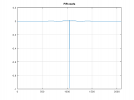
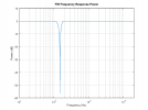
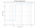
I generated an FIR filter that transitions the response from being +1 at low frequencies to -1 at high frequencies. It goes straight through zero on the way, so there's a null in the power response at the middle of the transition. Intuitively, the filter response makes perfect sense:

There's a big negative spike in the middle of the filter, with value of -1. That's why the high frequencies are 180 degrees out of phase with the signal. The sum of the filter coefficients is 1, which is why the low frequencies are in phase with the signal. So the rest of the coefficients have to sum to 2, to make up for the huge negative spike.

I'm not sure how many coefficients might be reasonable to use on little DSP boards. This filter has 2087 coefficients, but I could make it much smaller. As you can see, there's not much going on a the ends. I'd be very interested to see what a filter like this did for the efficiency and dispersion. I'd be happy to regenerate something with the appropriate sample rate and number of taps to be of use.

The Coefficients:

Bessel_FIR_coefs.png

The Power response:
Bessel_FIR_FreqRespPower.png

The phase response (delay removed):
Bessel_FIR_FreqRespPhase.png
 

DanielT

Major Contributor
Joined
Oct 10, 2020
Messages
4,820
Likes
4,749
Location
Sweden - Слава Україні
Note that a Bessel array is not a traditional line array. It has adequate vertical off-axis response as well, while a line array has very narrow directivity. If you have along array, that is not an issue.

Regarding distortion: from what I’ve seen elsewhere, it’s actually pretty good. The link you posted did not do a proper level matched comparison, and having 5 instead of one will help quite a bit as well.
As said regarding the test results Faital Pro, a pinch of salt.:)

Regarding less distortion. For example, the peerless mentioned, with it in a speaker say 16 speaker elements per box, the voltage sensitivity increases by 12 dB. It does a lot regarding the possibly audible distortion.

Several cheap subwoofers vs an expensive one. Same cost. What gives the best results?
Depends on a lot of factors then, so topic for another thread. :)
 
Last edited:
OP
voodooless

voodooless

Grand Contributor
Forum Donor
Joined
Jun 16, 2020
Messages
10,393
Likes
18,340
Location
Netherlands
I generated an FIR filter that transitions the response from being +1 at low frequencies to -1 at high frequencies. It goes straight through zero on the way, so there's a null in the power response at the middle of the transition. Intuitively, the filter response makes perfect sense:

There's a big negative spike in the middle of the filter, with value of -1. That's why the high frequencies are 180 degrees out of phase with the signal. The sum of the filter coefficients is 1, which is why the low frequencies are in phase with the signal. So the rest of the coefficients have to sum to 2, to make up for the huge negative spike.
That's pretty cool. It's a very sharp filter though, so not sure if that is what is needed. How did you construct it? A slowly changing filter should also get rid of the null I guess.
I'm not sure how many coefficients might be reasonable to use on little DSP boards. This filter has 2087 coefficients, but I could make it much smaller. As you can see, there's not much going on a the ends. I'd be very interested to see what a filter like this did for the efficiency and dispersion. I'd be happy to regenerate something with the appropriate sample rate and number of taps to be of use.
I think it can do something like 2k taps in total, so on 4 channels, that would be like 500. But possibly you can share some channels, so if one is a bit smart, you can do a bit more. But even with 500, I guess one can do some interesting things.

I do need to switch simulation software for this, I don't think BoxSim can do convolution. I'll double check.
 
Top Bottom