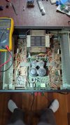
Hi. I am new to this forum and I'm not sure if I'm posting on the right spot or not but I have a NAD 2200 power envelop that my dad had and it's stuck in protection mode.
So far I've done research and found the 2 relays to be a common problem on it but I've unsoldered them and inspected and they are good.
Relays click when you power it on after it's been unplugged for a while but other than that they don't click.
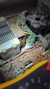
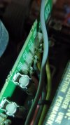
I looked for burnt circuits and I found that C208 and C208 capacitors have some burn marks under them. I pulled them out and tried plugging it in ant protection light went away which leads me to believe the problem is in that circuit. I then replaced the capacitors.
After doing so, same issue. I found that both of the 1 amp fuses (F605 and F606) were also blown.
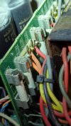
I jumpered across where the fuses were with a very fine wire to see if the capacitors fixed it, and then both of the capacitors I had just replaced popped.
Any help would be greatly appreciated
Thanks!
Caleb.
So far I've done research and found the 2 relays to be a common problem on it but I've unsoldered them and inspected and they are good.
Relays click when you power it on after it's been unplugged for a while but other than that they don't click.
I looked for burnt circuits and I found that C208 and C208 capacitors have some burn marks under them. I pulled them out and tried plugging it in ant protection light went away which leads me to believe the problem is in that circuit. I then replaced the capacitors.
After doing so, same issue. I found that both of the 1 amp fuses (F605 and F606) were also blown.
I jumpered across where the fuses were with a very fine wire to see if the capacitors fixed it, and then both of the capacitors I had just replaced popped.
Any help would be greatly appreciated
Thanks!
Caleb.