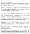
In our Test Lab, we typically use Chirp Sweep or Stepped Sweep to measure speaker frequency response or employ the Transfer Function method with voice signals to measure frequency response. However, due to specific requirements, we must adhere to IEC 60268-5 for speaker measurements. Currently, we are facing some difficulties with the Transfer Function test in Section 21.3. The main issue is that 21.3.2.2 requires the use of an impulse signal.
When using an impulse signal as the excitation signal for the Transfer Function test, we encounter triggering difficulties due to the impulse consisting of only one sample (48kHz sampling rate). Even if we manage to calculate the Transfer Function, the results are not clean. In contrast, using Pink Noise as the excitation signal provides clear and detailed Transfer Function results.
Therefore, we have some questions:
- Why does IEC 60268-5 Section 21.3 require the use of an impulse signal? Is it not possible to use other test signals?
- If an impulse signal must be used, how can we generate an impulse signal with a bandwidth of 20Hz to 20kHz?
- How can we reliably trigger an impulse response using Audio Precision's APx500 software?
