Finally on this sunny Sunday, I scheduled a time to share the ESS hump repair solution.
The following method only verifies the two SONCOZ DACs SGD1 and LA-QXD1, both of them using ES9038Q2M DAC chips, and the others are only referrals.
To save you time, first put forward the method and conclusion: For the ES9038Q2M DAC chip, adjusting the combination of resistance and capacitance values of its IV converter and LPF circuit can fix the hump problem,and it belongs to the hardware repair scheme.
The following is the process of my verification:
2019-12-10-13:30
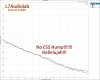
To start my validation and repair, first do nothing, look at the hump, it looks like this:

This hump is so ugly that I have overlooked this problem. Please forgive the unprofessional design process.The blue channel is the channel I started to adjust, and the red channel is the contrast channel, which is easy to distinguish.
I used two different OPAs in my design. First, I started changing the (IV and LPF) OPA’s placement. But unfortunately, the hump still stands out:

This is then verified using higher precision resistors. The resistance with 1% precision is used in the design. I have prepared for it and purchased a variety of resistance with 1‰ precision in advance.

The change of hump is not obvious, so it seems that the resistance precision is not to blame. Other work needs urgent attention at this time, so the verification work will be delayed a little.
2019-12-12 16:20
When I finally had time to continue my verification, I did some calculations, mainly the bandwidth calculations for the IV circuit. Normally, the larger the bandwidth design of the IV circuit, the more noise it may bring as a result, so the design should only meet the bandwidth of the audio signal. The design bandwidth of the IV circuit is around 130kHz, and I get good other parameters in this bandwidth, such as THD+N, linearity, SNR, crosstalk and so on.
I doubt that changing the bandwidth will bring the performance parameters I've already tuned to degrade the overall performance of the product.

The following is a manuscript of my calculations, in which I calculate various combinations of IV resistance and capacitance values in a bandwidth range of 130khzkz-500khz.

But the end result was a slap in the face, and the hump remained the same.
I decided to leave the IV circuit for a while and try to adjust the capacitance of the LPF circuit. The original design was 1nF and adjusted to 2.2nF, 3.3nF, and 4.7nF. It turned out that 2.2nF worked best, as follows:

The blue channel does go down, but that seems to be the limit of how far it can go down, and that's a big enough distance to be stationary.
Well, I think I'm hungry. I need to have dinner and clear my head.
2019-12-12 20:00
After dinner, I will continue to verify the bandwidth of the IV circuit. Who set the maximum bandwidth of 500kHz for me? Why don't I try it higher? I think there's a ghost here. I have to try it right now. I adjusted the capacitance of the IV circuit from 470pF to 100pF. Here's the result:

I couldn't believe my eyes and the hump had shrunk. I feel like I'm close to finding out the truth.
I then adjusted the capacitance on such a basis and found that the effect of the 150pF capacitor was optimized well:

However, the value of this capacitor is not some conventional value, and it may be difficult to purchase in mass production. Now that I have found the direction, and look at my messy laboratory, I think I need to sleep:

Well, get some sleep and continue the test tomorrow, 2019-12-12-22:30
2019-12-13 10:40
I kept the machine running last night to see how its thermal stability was:

The thermal stability is good, it doesn't affect the hump, which is good news.
According to the thinking and direction of yesterday, there is still a resistance of 100R in the IV circuit. There should also be room for adjustment of this parameter. Let's try to adjust to 75R first, as shown in the figure below:

It's getting smoother, it's showing up, keep checking, adjust 39R, look at the picture:

It's a little smoother and smoother. Happy. Keep going. 51R. Look at the picture:

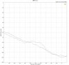
And finally, after a couple of tests. The capacitance value is set at 220pF and the resistance value is set at 51R. I feel that this is the result I want, so I modify the device of the two channels and adjust the output amplitude. The result is as follows:

So far, I think the hump problem has been solved, ignoring the channel difference caused by my manual welding. However, this hump is really so sensitive that it is hard to catch like a ghost. The adjustment of resistance and capacitance parameters is very small and hump changes a lot.
To verify my solution, I continued to experiment with the method on LA-QXD1. Again, the blue channel is the adjusted channel:

It looks amazing, it's smooth all at once, so I'm going to change the other channel, the red channel, and I'm going to look at the picture:

OK, I think the solution is feasible and verified here. I am very glad to share these experiences. It is a very interesting experience, and it also encourages me to truly achieve the product technology.
Finally, the circuit before and after the hump is pasted for comparison:

SGD1 and LA-QXD1 correct the hump in the same way, so the comparison diagram of SGD1 can be posted here. Of course, someone mentioned the possibility of a software fix before. I only tried to turn off and turn on the register related to the THD+N compensation of ES9038Q2M, and the result was no different. I think this is a pure hardware repair.
(* ̄︶ ̄)
The following method only verifies the two SONCOZ DACs SGD1 and LA-QXD1, both of them using ES9038Q2M DAC chips, and the others are only referrals.
To save you time, first put forward the method and conclusion: For the ES9038Q2M DAC chip, adjusting the combination of resistance and capacitance values of its IV converter and LPF circuit can fix the hump problem,and it belongs to the hardware repair scheme.
The following is the process of my verification:
2019-12-10-13:30
To start my validation and repair, first do nothing, look at the hump, it looks like this:
This hump is so ugly that I have overlooked this problem. Please forgive the unprofessional design process.The blue channel is the channel I started to adjust, and the red channel is the contrast channel, which is easy to distinguish.
I used two different OPAs in my design. First, I started changing the (IV and LPF) OPA’s placement. But unfortunately, the hump still stands out:
This is then verified using higher precision resistors. The resistance with 1% precision is used in the design. I have prepared for it and purchased a variety of resistance with 1‰ precision in advance.
The change of hump is not obvious, so it seems that the resistance precision is not to blame. Other work needs urgent attention at this time, so the verification work will be delayed a little.
2019-12-12 16:20
When I finally had time to continue my verification, I did some calculations, mainly the bandwidth calculations for the IV circuit. Normally, the larger the bandwidth design of the IV circuit, the more noise it may bring as a result, so the design should only meet the bandwidth of the audio signal. The design bandwidth of the IV circuit is around 130kHz, and I get good other parameters in this bandwidth, such as THD+N, linearity, SNR, crosstalk and so on.
I doubt that changing the bandwidth will bring the performance parameters I've already tuned to degrade the overall performance of the product.
The following is a manuscript of my calculations, in which I calculate various combinations of IV resistance and capacitance values in a bandwidth range of 130khzkz-500khz.
But the end result was a slap in the face, and the hump remained the same.
I decided to leave the IV circuit for a while and try to adjust the capacitance of the LPF circuit. The original design was 1nF and adjusted to 2.2nF, 3.3nF, and 4.7nF. It turned out that 2.2nF worked best, as follows:
The blue channel does go down, but that seems to be the limit of how far it can go down, and that's a big enough distance to be stationary.
Well, I think I'm hungry. I need to have dinner and clear my head.
2019-12-12 20:00
After dinner, I will continue to verify the bandwidth of the IV circuit. Who set the maximum bandwidth of 500kHz for me? Why don't I try it higher? I think there's a ghost here. I have to try it right now. I adjusted the capacitance of the IV circuit from 470pF to 100pF. Here's the result:
I couldn't believe my eyes and the hump had shrunk. I feel like I'm close to finding out the truth.
I then adjusted the capacitance on such a basis and found that the effect of the 150pF capacitor was optimized well:
However, the value of this capacitor is not some conventional value, and it may be difficult to purchase in mass production. Now that I have found the direction, and look at my messy laboratory, I think I need to sleep:
Well, get some sleep and continue the test tomorrow, 2019-12-12-22:30
2019-12-13 10:40
I kept the machine running last night to see how its thermal stability was:
The thermal stability is good, it doesn't affect the hump, which is good news.
According to the thinking and direction of yesterday, there is still a resistance of 100R in the IV circuit. There should also be room for adjustment of this parameter. Let's try to adjust to 75R first, as shown in the figure below:
It's getting smoother, it's showing up, keep checking, adjust 39R, look at the picture:
It's a little smoother and smoother. Happy. Keep going. 51R. Look at the picture:
And finally, after a couple of tests. The capacitance value is set at 220pF and the resistance value is set at 51R. I feel that this is the result I want, so I modify the device of the two channels and adjust the output amplitude. The result is as follows:
So far, I think the hump problem has been solved, ignoring the channel difference caused by my manual welding. However, this hump is really so sensitive that it is hard to catch like a ghost. The adjustment of resistance and capacitance parameters is very small and hump changes a lot.
To verify my solution, I continued to experiment with the method on LA-QXD1. Again, the blue channel is the adjusted channel:
It looks amazing, it's smooth all at once, so I'm going to change the other channel, the red channel, and I'm going to look at the picture:
OK, I think the solution is feasible and verified here. I am very glad to share these experiences. It is a very interesting experience, and it also encourages me to truly achieve the product technology.
Finally, the circuit before and after the hump is pasted for comparison:
SGD1 and LA-QXD1 correct the hump in the same way, so the comparison diagram of SGD1 can be posted here. Of course, someone mentioned the possibility of a software fix before. I only tried to turn off and turn on the register related to the THD+N compensation of ES9038Q2M, and the result was no different. I think this is a pure hardware repair.
(* ̄︶ ̄)
Attachments
Last edited:
 !!
!!