• WANTED: Happy members who like to discuss audio and other topics related to our interest. Desire to learn and share knowledge of science required. There are many reviews of audio hardware and expert members to help answer your questions. Click here to have your audio equipment measured for free!

Denon PMA-300V: [Fixed] Right Channel is still audible at 0 volume

catch22

Member
Forum Donor
Joined
Feb 10, 2024
Messages
68
Likes
29
Location
Ireland
Hi all,

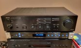
I have a Denon PMA-300V (a model from late 1980s). It works fine, except for one thing.

Symptoms:
1. When the volume knob is at 0 (5pm position), Left channel is fully silent, but the Right is still audible. Very quiet, but still audible
2. Note: this barely audible sounds like low frequences are gone, only high frequencies remain
3. No difference to the residual sound whether Loudness and Subsonic are pressed or not
4. Once the volume knob is just slightly off (5.30pm) both L and R sound equally, there is no disbalance, there is no lack in low frequency
5. [Update] It does respond to Balance knob, i.e. the residual sound in Right goes away when Balance is rotated to the Left

I was looking at chematics and tried to trace to Volume control. The version I downloaded from the internet is a low quality scan
@Doodski can you pls check if hifiengine has a better one?

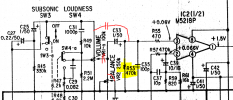
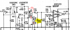
I hope I correctly traced through from 11/13 terminals of TC9152P (output from the input selector) to the Volume and Balance (yellow and red lines).
Is the Volume resistor the only suspect? Or can the leakage be because of some other component?
I have one doubt. If it was just the leaking volume resistor, would the "quiet sound" be full frequency? But it is just highs, no lows. So maybe something else?

This is not an expensive device, so it is more curiousity than necessity. No problem if it is never fixed.
But if experts can have a look, would be nice :)


@Doodski @Zapper @Dimitri @Glint and others? Thanks! :)
 

Attachments

  • 1710631713902.png
    1710631713902.png
    1.1 MB · Views: 32
  • 1710631856535.png
    1710631856535.png
    167 KB · Views: 33
  • 20240316_234051.jpg
    20240316_234051.jpg
    155.8 KB · Views: 36
Last edited:

Doodski

Grand Contributor
Forum Donor
Joined
Dec 9, 2019
Messages
21,640
Likes
21,916
Location
Canada
If you have not cleaned and lubricated the volume potentiometer yet then that is the very first thing to attack and service before doing anything else.
This stuff is good or if you have something else we can check that out and see what it is about and maybe use that instead.

This is the DeoxIT Series stuff.>

This is what you need to purchase if you do not have contact cleaner lubricant. It is safe on plastic so overspray should not mar your Denon.
 

Doodski

Grand Contributor
Forum Donor
Joined
Dec 9, 2019
Messages
21,640
Likes
21,916
Location
Canada
I emailed the 2 PDF docs service literature to your email address.
 

wwenze

Major Contributor
Joined
May 22, 2018
Messages
1,331
Likes
1,883
But it is just highs, no lows

Capacitive coupling. Something broke and enabled an alternative path for the signal.

First thing I'd do is measure the resistance of middle pin to gnd pin on the volume pot, it should read zero if volume is zero. If that already is zero, you can ignore everything before the volume pot. But this statement is only true if the gnd pin of the volume pot is properly connected to the rest of the amp, so I would also measure the resistance of gnd pin (right) and gnd pin (left), if resistance of that is zero too then there is no problem on that pin either.
 

Zapper

Addicted to Fun and Learning
Joined
Mar 4, 2023
Messages
608
Likes
837
When the volume knob is at 0 (5pm position), Left channel is fully silent, but the Right is still audible. Very quiet, but still audible
2. Note: this barely audible sounds like low frequences are gone, only high frequencies remain
3. No difference to the residual sound whether Loudness and Subsonic are pressed or not
3. Once the volume knob is just slightly off (5.30pm) both L and R sound equally, there is no disbalance, there is no lack in low frequency
Try one more thing: how does it respond to the balance knob? Turn the balance knob all the way to the left (maximum left volume, minimum right volume). Does that make the sound in the right channel go away?

I agree with @wwenze - the problem is capacitive coupling between the preamp and the input to the power amp. The wiper on the volume pot is apparently open or high impedance at the 0 volume position, due to dirt, wear, or oxidation, and can not short this capacitive signal to gnd at its minimum position. If the wiper on pot VR1-a is open, then stray capacitance from the preamp (between the leads in the potentiometer or between the traces of the PCB) can capacitively couple the preamp signal to the input of the amplifier. Without the pot wiper to short this node to gnd, it is loaded by R53 (470k) and the balance pot VR2. If the balance pot is in the middle of its range, it provides 125k to gnd. But if you turn it all the way to the left (as a test) it will provide ~0 ohms to gnd on the right channel input. This should short out the coupling capacitor and silence the right channel.

If that works, it confirms that the problem is in the wiper of the volume pot. @Doodski has the solution - hit it with the contact cleaner while rotating the volume up and down. Hopefully that will solve it. If that doesn't work, either ignore it or replace the pot. The resistance measurements that @wwenze suggests should be done to quantify the problem and to evaluate the effectiveness of the contact cleaner. The resistance between the wiper and ground should be ~0 at minimum volume.

1.PNG
 

Attachments

  • 1710641806912.png
    1710641806912.png
    128.9 KB · Views: 16
  • 1.PNG
    1.PNG
    113.7 KB · Views: 13
Last edited:
OP
C

catch22

Member
Forum Donor
Joined
Feb 10, 2024
Messages
68
Likes
29
Location
Ireland
Thank you all guys!

If you have not cleaned and lubricated the volume potentiometer yet then that is the very first thing to attack and service before doing anything else.
This stuff is good or if you have something else we can check that out and see what it is about and maybe use that instead.

This is the DeoxIT Series stuff.>

good stuff, will watch in the evening! Thanks for the manual, it is actually exactly the same scan I have. Probably, a higher quality scan does not exist.

Try one more thing: how does it respond to the balance knob? Turn the balance knob all the way to the left (maximum left volume, minimum right volume). Does that make the sound in the right channel go away?
Yes, it does respond to balance. When Balance knob is rotated to the left, this residual sound in Right goes away.
(i'll edit the first post as well to add this for future)

I agree with @wwenze - the problem is capacitive coupling between the preamp and the input to the power amp. The wiper on the volume pot is apparently open or high impedance at the 0 volume position, due to dirt, wear, or oxidation, and can not short this capacitive signal to gnd at its minimum position. If the wiper on pot VR1-a is open, then stray capacitance from the preamp (between the leads in the potentiometer or between the traces of the PCB) can capacitively couple the preamp signal to the input of the amplifier. Without the pot wiper to short this node to gnd, it is loaded by R53 (470k) and the balance pot VR2. If the balance pot is in the middle of its range, it provides 125k to gnd. But if you turn it all the way to the left (as a test) it will provide ~0 ohms to gnd on the right channel input. This should short out the coupling capacitor and silence the right channel.
Does this stray capacitance explain that the residual sound is not just "normal quiet", but limited frequency bandwidth (only highs)?
I will open and do measurements as you and @wwenze suggested.
Is it ok to measure without desoldering, won't other paths on the PCB impact the resistance?
 

Zapper

Addicted to Fun and Learning
Joined
Mar 4, 2023
Messages
608
Likes
837
Yes, it does respond to balance. When Balance knob is rotated to the left, this residual sound in Right goes away.
Good. Then the wiper of the volume pot is almost certainly the problem. The balance pot can pull the power amp input node (input to C33) all the way to GND but the volume pot can't, because of wiper resistance. Hopefully the contact cleaner will fix it.

Does this stray capacitance explain that the residual sound is not just "normal quiet", but limited frequency bandwidth (only highs)?
Yes. The stray capacitor I drew, plus the parallel resistance of VR2 and R53 (R = 1/(1/125k + 1/470k))= 99k), forms a 1st order high pass filter with a 6dB per octave. At higher frequencies (~16kHz), C35 will become significant to limit the gain. Above this frequency, the stray capacitance forms a capacitive voltage divider with C35, and the gain will be at its maximum. I'm guessing the stray cap is about 10pF. That makes the gain above 16kHz set by the capacitive divider: 10pf/(10pF+100pF) = 0.091 = -20.8dB, declining -6dB per octave below 16kHz. It might be more or less, depending on the actual value of the stray capacitance.

The 16kHz comes from the value of C35 (C=100pF) with the parallel resistance of VR2 (centered = 125k) and R53 (470k) (R=99k). That gives a pole frequency of 1/(2*Pi*99k*100pF) = 16kHz.

Is it ok to measure without desoldering, won't other paths on the PCB impact the resistance?
Yes. Just measure the resistance from the wiper node of the volume pot to ground, with the balance pot centered.
 

wwenze

Major Contributor
Joined
May 22, 2018
Messages
1,331
Likes
1,883
Resistors can be measured in-circuit usually, since they are 2-pin devices and the value you expect to get is often what is written on the resistor, or whatever your potentiometer knob is supposed to be. Zero will be zero.

Furthermore you have a working channel to reference against anyway.
 
OP
C

catch22

Member
Forum Donor
Joined
Feb 10, 2024
Messages
68
Likes
29
Location
Ireland
Oh look, we've got a toroidal transformer!
No idea what happended to those bent caps in the right side of the picture, I'm not the first owner. Poor guys! I didn't straighten them for now.
20240317_133255.jpg

20240317_133301.jpg


Now, I am terribly confused about the measurements.
If I got the pinout correct, it must be like below - pins 1 and 3 are both sides of the resistance, 2 is Pin, and 4 is Ground.
4 is ground indeed.
20240317_185922 (2).jpg

So, I expect the resistance between 1-3 measure FIXED value (100K) regardless of the position of the pin.
Which is not the case! In fact none of pairs 1-2, 1-3 and 2-3 measure a stable value in all volume positions from 0 to 40
So either I'm doing something wrong, or the pot is totally fckd up, with very erratic behavior.

Resistance between pins:Volume Min (0)Volume middleVolume Max (40)
1<--->38k0-4: growing from 8k to 10k
4-8: erratic jumps 10k down to 8k and back
8-12: growth from 10k to15k
12-16: decrease from 15k down to 200Ohm! (absolute bottom at position 16)
16:40: gradual increase from bottom 200Ohm to 39k
36k
1<--->246k0-22: Stable 46k
22-40: gradual decrease from 46k to 33k
33k
2<--->354k0-14: growth from 54k to 60k
14-36: drop from 60k to 14k
36-39: 12k to 400ohm
39-40: increase from 400ohm to 8k
8k
 
OP
C

catch22

Member
Forum Donor
Joined
Feb 10, 2024
Messages
68
Likes
29
Location
Ireland
Yes. The stray capacitor I drew, plus the parallel resistance of VR2 and R53 (R = 1/(1/125k + 1/470k))= 99k), forms a 1st order high pass filter with a 6dB per octave. At higher frequencies (~16kHz), C35 will become significant to limit the gain. Above this frequency, the stray capacitance forms a capacitive voltage divider with C35, and the gain will be at its maximum. I'm guessing the stray cap is about 10pF. That makes the gain above 16kHz set by the capacitive divider: 10pf/(10pF+100pF) = 0.091 = -20.8dB, declining -6dB per octave below 16kHz. It might be more or less, depending on the actual value of the stray capacitance.

The 16kHz comes from the value of C35 (C=100pF) with the parallel resistance of VR2 (centered = 125k) and R53 (470k) (R=99k). That gives a pole frequency of 1/(2*Pi*99k*100pF) = 16kHz.
Thanks a lot! This is a kind of info it will take me lots and lots of time to digest! But this is exactly what I am looking for in this excercise!! :)

This is the DeoxIT Series stuff.>
Any cheaper options? I do realise this makes lots of sense for repair shops, for a one time repair however.. it's 25e :) Can I try to pour IPA into it, rotate rotate and wait to dry?
 

Doodski

Grand Contributor
Forum Donor
Joined
Dec 9, 2019
Messages
21,640
Likes
21,916
Location
Canada
Nice lil amp. If me I would just squirt in the cleaner lubricant into ALL switches and controls and then check for success and then if required get techy on it. Do you have cleaner lubricant?
 

Doodski

Grand Contributor
Forum Donor
Joined
Dec 9, 2019
Messages
21,640
Likes
21,916
Location
Canada
Any cheaper options? I do realise this makes lots of sense for repair shops, for a one time repair however.. it's 25e :) Can I try to pour IPA into it, rotate rotate and wait to dry?
IPA like beer..LoL.
 

Doodski

Grand Contributor
Forum Donor
Joined
Dec 9, 2019
Messages
21,640
Likes
21,916
Location
Canada
Call up your local auto parts supplier, electrical supply or hardware store and request electrical contact cleaner and lubricant and it should cost substantially less there but not be a brand name like I suggested. Keep alert for any issues where the cleaner/lub will be a solvent for plastics and melt them.
 
OP
C

catch22

Member
Forum Donor
Joined
Feb 10, 2024
Messages
68
Likes
29
Location
Ireland
parts supplier, electrical supply or hardware store and request electrical contact cleaner and lu
this is the shop I used for caps. no have no other options, either this or amazon.co.uk. Have a look, anything from here?

OR
I tried googling the Denon part number 2119018004 - got nothing. By chance found something looking exactly the same. Must be it!
5 euro (1 euro part + 4 euro shipment)
 

Zapper

Addicted to Fun and Learning
Joined
Mar 4, 2023
Messages
608
Likes
837
Make sure the balance knob is in the middle and loudness is off.

One of the three terminals should be grounded in addition to pin 4. Find that one first. Then take measurements between the remaining two pins and gnd.
 
OP
C

catch22

Member
Forum Donor
Joined
Feb 10, 2024
Messages
68
Likes
29
Location
Ireland
IPA like beer..LoL.
Seriously, can I try? :) What I'm losing, can IPA make it worse? Most interesting for me is the erratic behaviour in the table above. Am I doing something wrong? The volume control acts normal other than the bleeding sound at 0...
 

Zapper

Addicted to Fun and Learning
Joined
Mar 4, 2023
Messages
608
Likes
837
Also turn the subsonic filter ON. That will capacitively isolate the volume pot.
 
OP
C

catch22

Member
Forum Donor
Joined
Feb 10, 2024
Messages
68
Likes
29
Location
Ireland
Make sure the balance knob is in the middle and loudness is off.

One of the three terminals should be grounded in addition to pin 4. Find that one first. Then take measurements between the remaining two pins and gnd.
Yep, measured with both Subsonic and Loudness off.
Ground (4) is never short with anything else.

Resistance betweenat Volume 0at Volume 20at Volume 40
4<--->15.58k5.3k5.39k
4<--->252k51k35k
4<--->32.2k15k37k
 

Doodski

Grand Contributor
Forum Donor
Joined
Dec 9, 2019
Messages
21,640
Likes
21,916
Location
Canada
Seriously, can I try? :) What I'm losing, can IPA make it worse?
If you don't mind immersing the entire amp in hot water to melt the dried out beer and then doing the controls clean and lub anyway fly at it...LoL.
 
Top Bottom