• WANTED: Happy members who like to discuss audio and other topics related to our interest. Desire to learn and share knowledge of science required. There are many reviews of audio hardware and expert members to help answer your questions. Click here to have your audio equipment measured for free!

“some amps run out of current first and some run out of voltage first” get me confused.

Interesting question.

"running out of current" is generally (not always) a situation where the designers have deliberately included current limiting circuitry. That can be anything from benign to quite nasty sounding as the OPT devices are starved of drive due to circuitry detecting excess (to design paramters) current flow in the output devices.

Voltage limiting is simply (in most cases) sagging rails, and that is generally quite benign also, but squashes dynamics and allow a rapid onset of clipping, but almost in a 'soft' way- often accompanied by mains (60/120Hz) hum and noise at high levels modulating the music.

In modern Class Ds, the limiting is a completely different animal. Excess current is a trip situation, resulting in silence. Voltage limiting is perhaps not an issue except with ultra high power amps being run into no load.
This.

IME, in most (not all!) cases, voltage clipping simply clips the output, with a feedback penalty that is usually (not always!) relatively benign. Uncompensated (i.e. not due to the usual current-limiting circuitry) current clipping (which often enough leads to voltage clipping) starves devices and opens the feedback loop in a different way often more detrimental to the output. The issue I have seen is that voltage clipping recovers quickly and cleanly for the most part, whilst current clipping causes more output ringing and longer recovery times. Current limiting is intrinsic to most designs IME. It has been some time since I have tested this, however, so my experience may be out of date.

And yah, as @restorer-john said, class D amps clip differently, and usually have more protection circuits built into the design to handle it.

FWIWFM - Don
 
In a very basic sense you have an amplifier and it has DC rail voltage. Think of the traditional AC sine wave signal, the DC rail voltage defines how tall that sine wave can get. (Either between rail voltage and a reference of ground potential zero, or a usually equally positive and negative voltage.) Gain of the amplifier (and any upstream preamp) determines the amplitude of the sine wave, but it can only get so big; a transistor cannot get more off than totally off, and it cannot conduct infinitely or beyond. So if you increase gain beyond your rail voltage, your sine wave peaks will be clipped and your sound will be bad.

I.e. Let's say you have a rail voltage of 12 volts. If you have an input signal amplitude of 1 volt and a gain of 5, your output signal amplitude will be 5 volts. If you preamplify the signal to 2 volts (with a gain of 5) your output signal amplitude will be 10 volts. If you stuck with the 1 volt input but increased your amplifier gain (I won't get into how) to 10, you again have a 10 volt output. If you were to increase gain to 15 (or increase the input to accomplish the same thing) you're going to clip the output at 12 volts and the sine wave shape will start looking more square. That is 'running out of voltage' in a nutshell. You can (within limits) adjust the rail voltage of the amp design, this is most easily done with the input transformer for a linear power supply or by bucking up voltage in an SMPS before rectification; if you have an amp with a DC power supply for the most part all you can do is switch out the power supply for higher DC voltage.

Now, you are not hopefully just outputting your amplified signal into an oscilloscope, you're sending it to a load, i.e a speaker or headphones. That load has impedance, i.e. it can flow current between its terminals, but there is resistance that varies based on the frequency of the signal. Since we don't really care about the frequency here we can just think of it as a simple single resistance value. As your amplifier produces output voltage, it tries to apply it across the load, and that generates current as a function of that voltage and the resistance. Think of it like a bucket with a hole in the bottom, as you increase 'voltage' by increasing the water level in the bucket, the current water rushes out the hole more quickly. (In this case some buckets operate upside down and backwards so don't think too hard about it.) Now, here is the key: in order to maintain the output voltage on the load, the amplifier must be able to supply that current. Otherwise, it is as if you couldn't fill the bucket fast enough to overcome the hole, and the level would drop from where you want it. Again your sine wave signal starts looking all squished and screwy.

While output voltage is a fairly simple function of the amplifier design, current supply is a bit more complicated function mainly of the power supply. For a common rectified linear power supply, you depend on capacitors that charge when AC input (again, generally downstream of a transformer, not straight from your wall) is above rail voltage, and discharge when AC is lower, to maintain the DC voltage constant. With an SMPS you are (at high frequency) pulsing energy into a larger capacitor bank while the output current is draining it down. Each design has a finite amount of current it can supply, in the very short term (think fractions of the 60hz input AC cycle) or in the longer term (many 60hz AC cycles.) But you also have internal resistances that can limit current (and drop voltage as they do so) and current through resistance makes heat, which usually makes resistance go up, which drops more voltage internally, etc. So if your power supply is too small, you cannot meet current demand and output voltage collapses, but also as your amp gets too hot it can also get weaker. (Or it can work the other way and go into thermal runaway, which is worse.)

Not only does the distorted wave sound bad, but also the driven load (speaker) is generally designed to need that AC signal to move back and forth reasonably, generating smooth counterelectromotive force and avoiding heat buildup in the motor / voice coil. The distorted / squared off signal is, essentially, the original sine wave plus a lot of higher order harmonics added together. This can sound bad if audible and in general ends up making a bunch of heat, basically because eventually the speaker can't move fast enough to consume the energy as movement. In a multi-way speaker these higher-order harmonics get filtered out from the woofer by the crossover, but they hit the tweeters full blast, which is why clipped signals or 'not having enough amp' tends to fry tweeters. (Lots of things fry tweeters.)

Thank you for your patient answer. Your reasoning is clear, the metaphors are vivid, and the details are rich. You have explained various obscure concepts and theories as much as possible, which also clarifies my thinking.

I understand well the situation of overload due to too large an output signal, which is the case of "insufficient voltage." However, when considering the situation of "insufficient current," I tried to calculate with an example:

Amplifier: FiiO K3. According to the tests on this website, it can output 74mW of undistorted power under a 50-ohm load, and 13mW of power under a 300-ohm load. (It seems unable to output undistorted power because, according to this chart, the signal output by the DAC seems to be limited, and there is no sharp increase in distortion rate in the chart). This might be a relatively weak amplifier for open-back headphones.
Fiio K.png


Headphones: HIFIMAN HE-6SE. According to the table on DIYAudioHeaven, it has an impedance of 50 ohms and a sensitivity of 86dB/mW.


截屏2024-01-25 12.51.38.png

截屏2024-01-25 12.51.47.png


My confusion is, when the K3 drives the HE-6SE to produce a sound of 104.69dB (such as a 0dBFS 1kHz sine wave, or high dynamic music reaching 0dBFS peak, or severely compressed dynamic pop music reaching 0dBFS peak), is this sound distorted due to "exhausting the current" or "exhausting the voltage"? What about the situation where the sound is less than 104.69dB? (It seems unable to exceed 104.69dB) I sincerely hope to get your answer, thank you!
 
Thank you for your patient answer. Your reasoning is clear, the metaphors are vivid, and the details are rich. You have explained various obscure concepts and theories as much as possible, which also clarifies my thinking.

I understand well the situation of overload due to too large an output signal, which is the case of "insufficient voltage." However, when considering the situation of "insufficient current," I tried to calculate with an example:

Amplifier: FiiO K3. According to the tests on this website, it can output 74mW of undistorted power under a 50-ohm load, and 13mW of power under a 300-ohm load. (It seems unable to output undistorted power because, according to this chart, the signal output by the DAC seems to be limited, and there is no sharp increase in distortion rate in the chart). This might be a relatively weak amplifier for open-back headphones.
View attachment 344831

Headphones: HIFIMAN HE-6SE. According to the table on DIYAudioHeaven, it has an impedance of 50 ohms and a sensitivity of 86dB/mW.


View attachment 344829
View attachment 344830


My confusion is, when the K3 drives the HE-6SE to produce a sound of 104.69dB (such as a 0dBFS 1kHz sine wave, or high dynamic music reaching 0dBFS peak, or severely compressed dynamic pop music reaching 0dBFS peak), is this sound distorted due to "exhausting the current" or "exhausting the voltage"? What about the situation where the sound is less than 104.69dB? (It seems unable to exceed 104.69dB) I sincerely hope to get your answer, thank you!
Undistorted output per Amir's ASR test:
74 mW into 50 ohms = 1.924 V, 0.0385 A
13 mW into 300 ohms = 1.975 V, 0.00658 A

The voltage in these two cases is similar so that is probably about the most voltage it can output. The voltage is sagging some at 50 ohms, so there may also be some current limiting, but there is also a voltage divider with the amplifier's output impedance (unknown to me). We do know it is not distorting at this level per the review so any limiting (voltage or current) is not significant. With no other information (I did not look for the review), we cannot tell if the output voltage sag is due to current limiting, or if the amplifier's output impedance is causing the voltage to drop into the lower-impedance load. But since the 74 mW into 50 ohms measurement is undistorted, then if your headphones are distorted at that level, it is not the amplifier but the headphones themselves distorting.

At lower levels the amplifier would be distorting even less so again any distortion you hear would be due to the headphones and not the amplifier.

The situation is more complex since the headphone's impedance is probably not exactly 50 ohms at all frequencies, but a simple first-order look says any distortion at 104 dB SPL or below is from the headphones and not the amp. Like speakers, headphones have physical limits that determine how loudly they can sound without distortion, and you may be exceeding those limits.

HTH - Don
 
Thank you for your patient answer. Your reasoning is clear, the metaphors are vivid, and the details are rich. You have explained various obscure concepts and theories as much as possible, which also clarifies my thinking.

I understand well the situation of overload due to too large an output signal, which is the case of "insufficient voltage." However, when considering the situation of "insufficient current," I tried to calculate with an example:

Amplifier: FiiO K3. According to the tests on this website, it can output 74mW of undistorted power under a 50-ohm load, and 13mW of power under a 300-ohm load. (It seems unable to output undistorted power because, according to this chart, the signal output by the DAC seems to be limited, and there is no sharp increase in distortion rate in the chart). This might be a relatively weak amplifier for open-back headphones.
View attachment 344831

Headphones: HIFIMAN HE-6SE. According to the table on DIYAudioHeaven, it has an impedance of 50 ohms and a sensitivity of 86dB/mW.


View attachment 344829
View attachment 344830


My confusion is, when the K3 drives the HE-6SE to produce a sound of 104.69dB (such as a 0dBFS 1kHz sine wave, or high dynamic music reaching 0dBFS peak, or severely compressed dynamic pop music reaching 0dBFS peak), is this sound distorted due to "exhausting the current" or "exhausting the voltage"? What about the situation where the sound is less than 104.69dB? (It seems unable to exceed 104.69dB) I sincerely hope to get your answer, thank you!
There is no simple repeatable rule for headphone distortion derived from amplifier behaviour unless the amplifier is operating outside its safe behaviour.

Putting it another, imagine a perfect amplifier, with zero output impedance able to swing 20V into any headphone and able to sustain currents of 5A into any headphone all without distortion. The headphones will still distort because their own finite driver and case limitations. The distortion has nothing to do with the amplifier.
 
My confusion is, when the K3 drives the HE-6SE to produce a sound of 104.69dB (such as a 0dBFS 1kHz sine wave, or high dynamic music reaching 0dBFS peak, or severely compressed dynamic pop music reaching 0dBFS peak), is this sound distorted due to "exhausting the current" or "exhausting the voltage"? What about the situation where the sound is less than 104.69dB? (It seems unable to exceed 104.69dB) I sincerely hope to get your answer, thank you!

K3 in SE (3.5mm) can deliver 1.96V in 32ohm
K3 in bal (2.5mm TRRS) can deliver 2.53Vrms in 32ohm (110mA rms)
FiiO also specs in 16ohm so given the low output voltage and ability to provide current in low imp. headphones it is clearly designed to be used with low imp headphones.

The amp section can deliver 140mA so 32ohm and higher will not current limit the amp section. 50 ohm is higher so less current and in balanced out it should be able to reach 3.8V in 50ohm.

With 91dB/V sensitivity this means the HE6SE can reach max 102.5dB when used balanced and max 96.5dB from the 3.5mm output.
Meaning with music and when using EQ you can only play somewhat loud before reaching the output voltage limit (clipping level).
95dB peaks is NOT loud and means average music levels could be between 75 and 85dB SPL depending on the recording (3.5mm out) add 6dB for balanced out.

The HE6SE will not distort here at all, you will experience the maximum that the K3 can reach.
 
Last edited:
K3 in SE (3.5mm) can deliver 1.96V in 32ohm
K3 in bal (2.5mm TRRS) can deliver 2.53Vrms in 32ohm (110mA rms)
FiiO also specs in 16ohm so given the low output voltage and ability to provide current in low imp. headphones it is clearly designed to be used with low imp headphones.

The amp section can deliver 140mA so 32ohm and higher will not current limit the amp section. 50 ohm is higher so less current and in balanced out it should be able to reach 3.8V in 50ohm.

With 91dB/V sensitivity this means the HE6SE can reach max 102.5dB when used balanced and max 96.5dB from the 3.5mm output.
Meaning with music and when using EQ you can only play somewhat loud before reaching the output voltage limit (clipping level).
95dB peaks is NOT loud and means average music levels could be between 75 and 85dB SPL depending on the recording (3.5mm out) add 6dB for balanced out.

The HE6SE will not distort here at all, you will experience the maximum that the K3 can reach.
There is no simple repeatable rule for headphone distortion derived from amplifier behaviour unless the amplifier is operating outside its safe behaviour.

Putting it another, imagine a perfect amplifier, with zero output impedance able to swing 20V into any headphone and able to sustain currents of 5A into any headphone all without distortion. The headphones will still distort because their own finite driver and case limitations. The distortion has nothing to do with the amplifier.
Undistorted output per Amir's ASR test:
74 mW into 50 ohms = 1.924 V, 0.0385 A
13 mW into 300 ohms = 1.975 V, 0.00658 A

The voltage in these two cases is similar so that is probably about the most voltage it can output. The voltage is sagging some at 50 ohms, so there may also be some current limiting, but there is also a voltage divider with the amplifier's output impedance (unknown to me). We do know it is not distorting at this level per the review so any limiting (voltage or current) is not significant. With no other information (I did not look for the review), we cannot tell if the output voltage sag is due to current limiting, or if the amplifier's output impedance is causing the voltage to drop into the lower-impedance load. But since the 74 mW into 50 ohms measurement is undistorted, then if your headphones are distorted at that level, it is not the amplifier but the headphones themselves distorting.

At lower levels the amplifier would be distorting even less so again any distortion you hear would be due to the headphones and not the amplifier.

The situation is more complex since the headphone's impedance is probably not exactly 50 ohms at all frequencies, but a simple first-order look says any distortion at 104 dB SPL or below is from the headphones and not the amp. Like speakers, headphones have physical limits that determine how loudly they can sound without distortion, and you may be exceeding those limits.

HTH - Don
Thank you for your patient answers! This has given me a deeper understanding of the electrical phenomena that occur when driving headphones and has made me more impressed with the scientific and objective measurement methods of this website, which has really opened many people's eyes!

But please forgive my dullness, as my brain cannot imagine the possibility of an amplifier driving headphones and causing clipping due to "insufficient current"... It seems like for any amplifier, when driving a specific pair of headphones, if the output energy is insufficient, the result is only that the sound is low. I hope you can give me a specific and typical example of clipping due to "insufficient current," thank you!
 
I hope you can give me a specific and typical example of clipping due to "insufficient current," thank you!
"Clipping" is not the best term. If you think about clipping visually, imagine a voltage sine wave, where the top and bottom are clipped off. This isn't really happening in the current sense. So think of clipping for insufficient voltage, and current limits for insufficient current. The sound impact is different.

Perhaps think about an amplifier powered by batteries. Imagine the power comes from 12 AAA cells in series. This gives a small current, but 18V so probably won't voltage clip. With a high impedance headphone, this may be adequate. With a low impedance headphone, the amplifier will be quiet and the battery will go flat quickly. The same thing with D2 cells will go louder and last longer
 
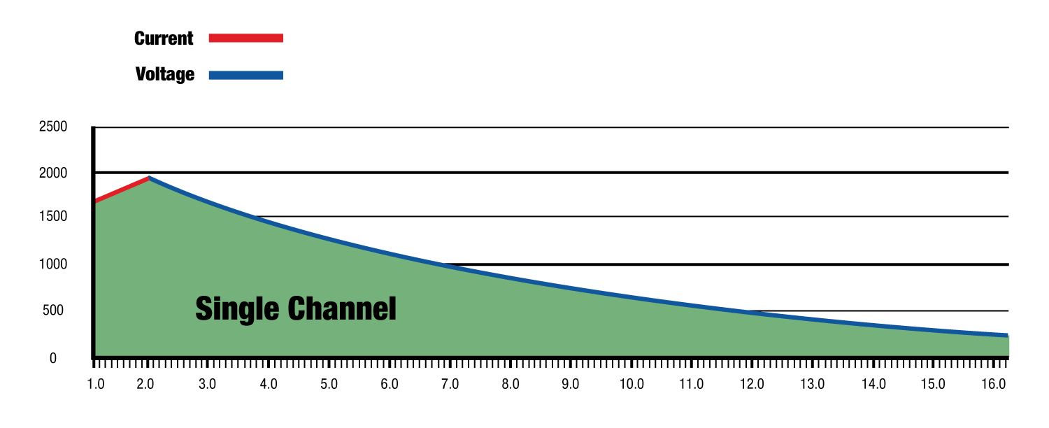
Although this prosound example is a loooong way from a headphone amp, i think it's still good for helping to visualize voltage and current limitations.
The 4 channel amp allows channels to be either bridged together, or run in parallel together. I think Hypex might have just introduced such a model, at CES 2024.

On the graph below, various channel configs/combinations are shown. FAST stands for Flexible Amplifier Summing Technology.
Red lines are voltage limits vs impedance. Blue curves the current limits.
Wattage on the Y axis

Graph came from this article, which is a pretty good explainer (despite the marketing lol)

FAST amp chart.JPG
 
Thank you for your patient answers! This has given me a deeper understanding of the electrical phenomena that occur when driving headphones and has made me more impressed with the scientific and objective measurement methods of this website, which has really opened many people's eyes!

But please forgive my dullness, as my brain cannot imagine the possibility of an amplifier driving headphones and causing clipping due to "insufficient current"... It seems like for any amplifier, when driving a specific pair of headphones, if the output energy is insufficient, the result is only that the sound is low. I hope you can give me a specific and typical example of clipping due to "insufficient current," thank you!
Very hand-waving simplified version: A headphone amplifier can only put out so much power before it limits. Power is the product of voltage and current, and is related to resistance. Clipping can be caused whenever any of those variables is exceeded.

P = power, V = voltage, I = current, R = resistance (impedance)

P = V * I
V = I *R -- if I is too low, then the amp cannot deliver enough V for a given R
I = V / R -- if R is too low, then I gets very large for given voltage and exceeds the amplifier's current limits
P = V^2 / R = I^2 * R

Let power be 1 W and look at the limits. If R is 0 ohms, then you need infinite current to deliver 1 W. If R is infinite, you need infinite voltage to deliver 1 W. In between, when you turn up the volume you could exceed the amplifiers voltage or current limits depending upon the amplifier's design and value of R (impedance of the headphones). Any time you clip for any reason the sound will be bad.

If you overdrive the headphones, the diaphragms will exceed their physical limits, that is they cannot move any further no matter how much power you apply. At that point sound will also be "clipped" but by the headphones instead of the amplifier.

HTH - Don
 
I hope you can give me a specific and typical example of clipping due to "insufficient current," thank you!

index.php

here you can see current limiting at work.
 
This might be redundant... I didn't read all of the posts...

Since current and voltage are tied-together (Ohm's Law), if one clips the other also clips. Both would be "squared off" if viewed as waveforms. We don't always know which is the cause and which is the effect but it can be deduced from test results.

It's easier to "look at" the voltage with an oscilloscope and most distortion analyzers are reading/monitoring the voltage.
 
If the supply voltage drops the current drops. If the current demand exceeds the supply capability, the voltage sags.
Well yes it does. But if this is because of current limit - it is not a voltage limit. If the amp could supply more current, then the voltage wouldn't sag.

All amps have a max possible voltage, and a max possible current. Either limit can be hit first depending on the load impedance.
 
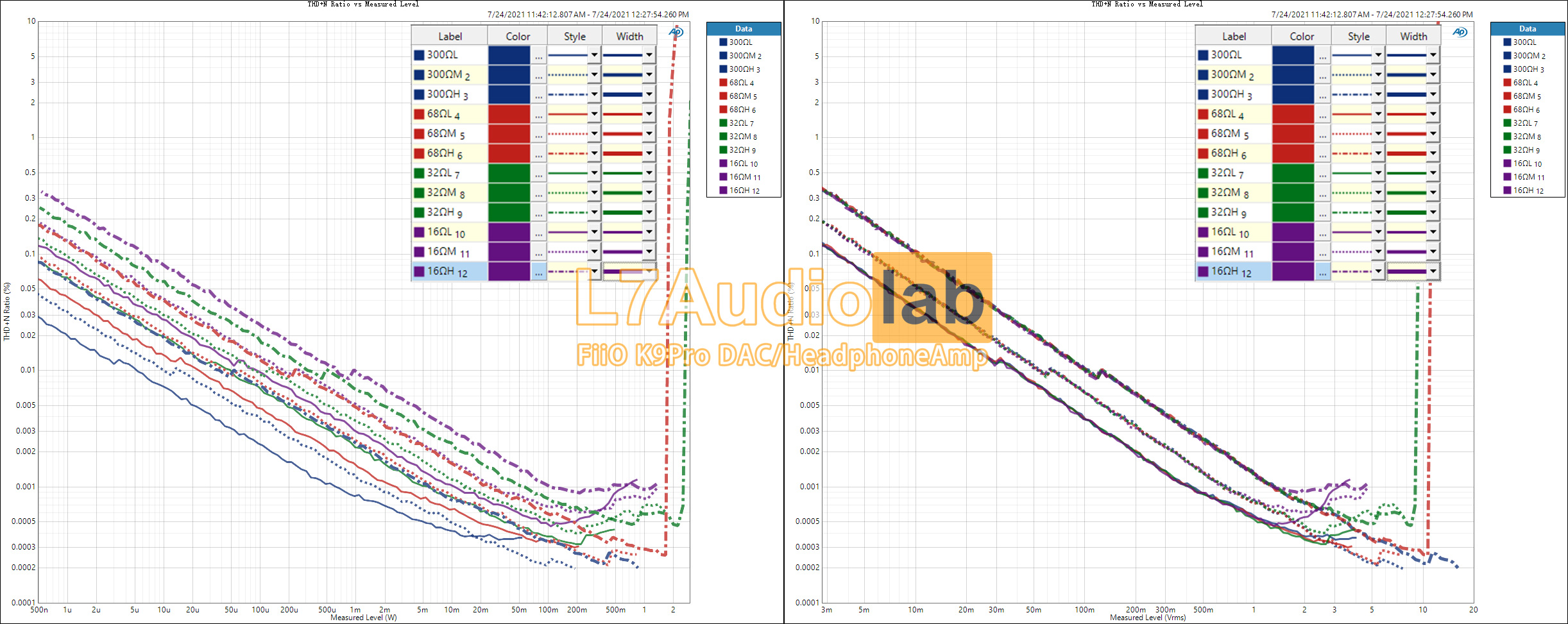
A bit of a necropost, but on topic, could someone explain what could be going on with this graph from https://www.l7audiolab.com/f/fiio-k9pro/?

THDN-Ratio-vs-Measured-Level-ALL.jpg


I presume this was measured using the K9 Pro's internal DAC driving the THX 788+ amp section. I presume that when a trace ends with a sharp vertical rise, hard clipping has been hit, but when the trace ends without such, it is because the internal DAC was not able to drive the amp into either voltage or current limited clipping. Given this, I would have expected clipping to have been observed for the 300 Ohm and 16 Ohm loads for voltage and current limited clipping respectively, yet here, it is only the intermediate 68 Ohm and 32 Ohm loads that clip on high gain, and for different powers and voltages.

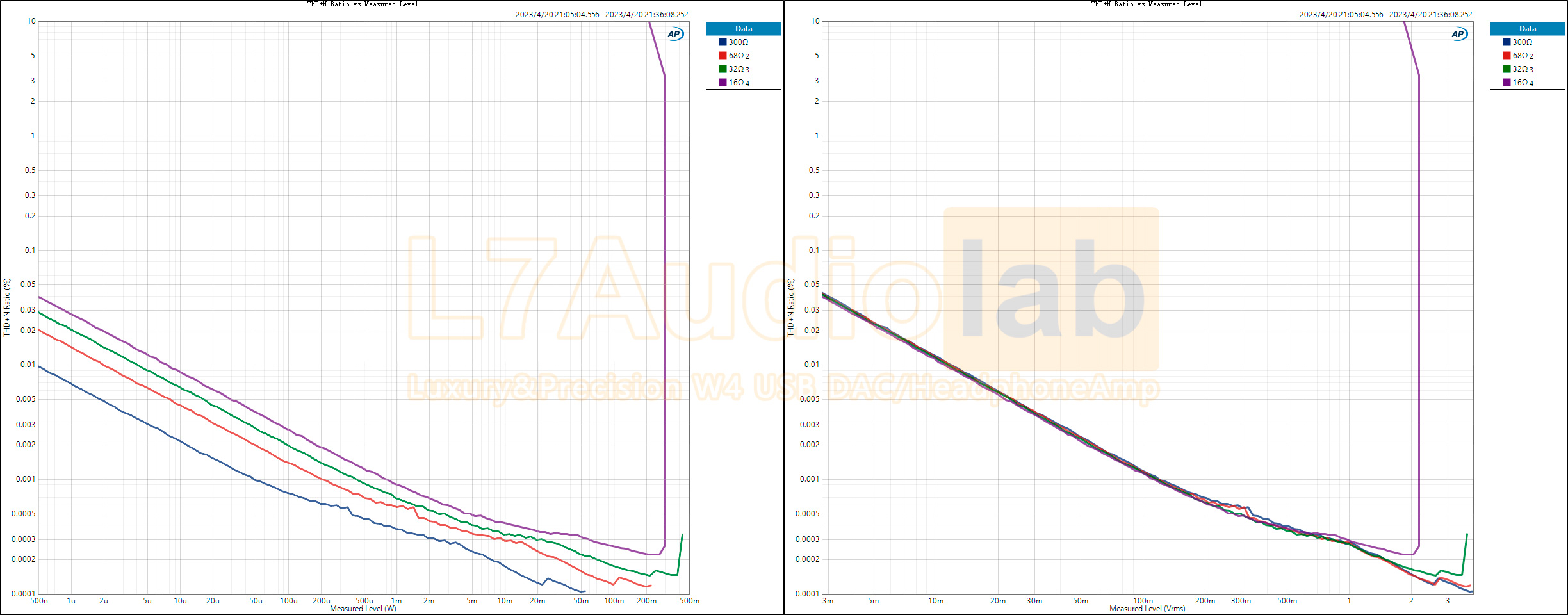
For their amp measurements like with https://www.l7audiolab.com/f/topping-l70/, it seems apparent that the external testing DAC most likely used is able to clip said amp for all loads, while with https://www.l7audiolab.com/f/lpw4/, I suppose that this showed that the internal DAC could only drive the amp section to the point of current clipping for the 16 Ohm load.

1682090535-THDN-Ratio-vs-Measured-Leve.jpg
 
Back
Top Bottom