• WANTED: Happy members who like to discuss audio and other topics related to our interest. Desire to learn and share knowledge of science required. There are many reviews of audio hardware and expert members to help answer your questions. Click here to have your audio equipment measured for free!

Relays that are "audiophile" grade

MakeMineVinyl

Major Contributor
Joined
Jun 5, 2020
Messages
3,558
Likes
5,875
Location
Santa Fe, NM
These are reed relays right? Any suggestions for gold contact relays? I don't seem to be able to find any on Mouser or Digikey.
The ones I have are reed relays I believe. I did a quick search but couldn't find them. There's also the tried and true solid state solution of DG308B / DG309B.
 
Last edited:

audio2design

Major Contributor
Joined
Nov 29, 2020
Messages
1,769
Likes
1,832
Something to keep in mind is to use a small signal relay. Better quality ones have different surface treatments on the contacts. Relays to switch power can have issues with contact resistance when they repeated do not switch power.
 
OP
S

starfly

Senior Member
Forum Donor
Joined
Jun 6, 2019
Messages
353
Likes
289
The ones I have are reed relays I believe. I did a quick search but couldn't find them. There's also the tried and true solid state solution of DG308B / DG309B.

If I was going to use two separate relays, one per input source, so they're truly isolated and the chance of crosstalk is nihl, what would you recommend? The Vishay ones you linked would be for a one relay solution (though I guess, I could still order two of them and design the circuit appropriately).

And most of the reed relays I found on Mouser/Digikey have rhodium contacts. Not sure to what extent that's better or worse than gold.
 

MakeMineVinyl

Major Contributor
Joined
Jun 5, 2020
Messages
3,558
Likes
5,875
Location
Santa Fe, NM
If I was going to use two separate relays, one per input source, so they're truly isolated and the chance of crosstalk is nihl, what would you recommend? The Vishay ones you linked would be for a one relay solution (though I guess, I could still order two of them and design the circuit appropriately).

And most of the reed relays I found on Mouser/Digikey have rhodium contacts. Not sure to what extent that's better or worse than gold.
The ones on Digikey should be OK, but you should check the data sheets to be sure. DG308s and DG309s are sometimes used in pairs, the 308 connecting the signal, and the 309 shorting the unused output to ground (after an appropriate build-out resistor!!!). They were heavily used in professional mixing consoles and work very well. If you have build-out resistors, you'd need a unity gain buffer on the output to provide a low output impedance.
 

Colin James Wonfor

Active Member
Technical Expert
The Wonf
Joined
Oct 24, 2016
Messages
210
Likes
182
Location
London< UK
On the Tellurium Q Listen Pre Amp I used them and used a reset thyristor circuit to control them and auto select active circuit, it worked well. I try and find cct and out up. OK found it TH1-4 are TO92 Thyristor not transistors, 1A @ 100v.
Using OPTO FET,s will give nice isolation and a massive overload potential were as the DG series will not. I used a long time ago CD 4016/4066 and CD4052/ and they clip at 6.2V peak- peak. OK for most thing but now you can do better.
If you use the DG series in a virtual earth arrangement then there should be no problems as in Mixer Desks.
Some of the Maxim device are good also, lots to choose from check on leakage capacitance this can and does cause problems.
 

Attachments

  • baby a class headphone amp.pdf
    939 KB · Views: 142
Last edited:

Colin James Wonfor

Active Member
Technical Expert
The Wonf
Joined
Oct 24, 2016
Messages
210
Likes
182
Location
London< UK
As to relay as audio2design says the chemical make up can cause problem, Silver sound OK but they do oxidize , Rhodium is fair, by Beryllium Copper Gold plate works the best. Gold must be plated on Nickel substrate type, Pickering did do those once not sure now and Douglas Randal did now Crydom. Mercury is good but toxic if broken and wrecks gold.
Platinum is OK but what price fheeew, and never expose Platinum to Methane .

I hope this gooble gook helps


MakeMineVinyl

Major Contributor
Joined
Jun 5, 2020
Messages
3,558
Likes
5,875
Location
Santa Fe, NM
Using OPTO FET,s will give nice isolation and a massive overload potential were as the DG series will not.
The "B" revisions of the DG 308/9 will not overload until the analog signal is +- 15 volts per the data sheet. True, they do not provide isolation. We researched using them in a recent design.
 
OP
S

starfly

Senior Member
Forum Donor
Joined
Jun 6, 2019
Messages
353
Likes
289
Ok, sticking with that Omron relay for a moment, that I linked earlier, but now using 2 (for perfect isolation) along with a flyback diode (is the second redundant?), is this the right way to wire it all up?

1633039081856.png
 

Attachments

  • 1633038792378.png
    1633038792378.png
    16 KB · Views: 85

Colin James Wonfor

Active Member
Technical Expert
The Wonf
Joined
Oct 24, 2016
Messages
210
Likes
182
Location
London< UK
That will work, but you can reduce some noise not much but a bit, by linking the unused pin on the relays via load resistor to ground, there also seems to be a problem, you could just use one relay as a change over device save money ,and one less diode.
When laying PCB interleave a ground track like a guard ring around and along the signal track and in-between them. Grounded only at one end.
It reduce cross talk and interference.
 
OP
S

starfly

Senior Member
Forum Donor
Joined
Jun 6, 2019
Messages
353
Likes
289
That will work, but you can reduce some noise not much but a bit, by linking the unused pin on the relays via load resistor to ground, there also seems to be a problem, you could just use one relay as a change over device save money ,and one less diode.
When laying PCB interleave a ground track like a guard ring around and along the signal track and in-between them. Grounded only at one end.
It reduce cross talk and interference.
Thanks, this will be my first time designing a PCB, and I'll try to figure out what you're suggesting. Will post a diagram here once I have a drawing worked up.

As for that load resistor, what kind of resistor would that be exactly? Would any kind suffice? Apologies if these all seem like very basic questions, but I don't really know much about all this stuff :) I am in the process of educating myself a bit more, though.
 

MakeMineVinyl

Major Contributor
Joined
Jun 5, 2020
Messages
3,558
Likes
5,875
Location
Santa Fe, NM
Ok, sticking with that Omron relay for a moment, that I linked earlier, but now using 2 (for perfect isolation) along with a flyback diode (is the second redundant?), is this the right way to wire it all up?

View attachment 156434
So this is intended to switch between two sources? The way its shown, input #1 is 'on' with no +12V and input #2 is 'on' with +12V. Are pins 1 and 2 on the input and outputs the left and right channels? You have all grounds (except for the +12V ground) tied together, right?
 
OP
S

starfly

Senior Member
Forum Donor
Joined
Jun 6, 2019
Messages
353
Likes
289
So this is intended to switch between two sources? The way its shown, input #1 is 'on' with no +12V and input #2 is 'on' with +12V. Are pins 1 and 2 on the input and outputs the left and right channels? You have all grounds (except for the +12V ground) tied together, right?

Pins 1 and 2 are L and R channels. And correct, input 1 is essentially a NC circuit, and input 2 a NO circuit. Input 1 would be for my DAC, and that would be the default signal. And then when I turn on my AVR, that sends a 12V trigger, opening the #1 circuit, and closing the #2 circuit, so then routing the AVRs audio to my amp.

And I think I have all the grounds tied together. Does it not look that way?
 

MakeMineVinyl

Major Contributor
Joined
Jun 5, 2020
Messages
3,558
Likes
5,875
Location
Santa Fe, NM
Pins 1 and 2 are L and R channels. And correct, input 1 is essentially a NC circuit, and input 2 a NO circuit. Input 1 would be for my DAC, and that would be the default signal. And then when I turn on my AVR, that sends a 12V trigger, opening the #1 circuit, and closing the #2 circuit, so then routing the AVRs audio to my amp.

And I think I have all the grounds tied together. Does it not look that way?
I didn't see the grounds referenced at all. You should have the grounds all tied to a single point except for the +12V ground, as mentioned above, and you should then make a ground pour across the entire PCB (except for the screw mounting holes for the PCB) which is connected only to that central ground point and nothing else. A two sided PCB would easily do it, or even a single sided one for that matter. A double sided board would allow you to get complete ground plane coverage in land-locked areas by the use of vias. Are you etching the boards yourself or sending them out? I use Advanced Circuits for my prototype boards, and they do a good job.

When tying the grounds of two components together you should pay attention to the potential of ground loops.
 
Last edited:

0bs3rv3r

Active Member
Joined
Oct 24, 2019
Messages
248
Likes
234
I am thinking you might try keeping the 12 volt input isolated. It doesn't need to be grounded just to operate the coils, and if it connects to the signal ground at the triggering amp, then you will be forming a ground loop between the trigger and signal cables.

Join the signal grounds together and connect to the case (should be metal) so the device maintains the shield continuity of the cables between the equipment.

and to answer an earlier question, yes I think only one flyback diode is really necessary for the parallel coils.
 
OP
S

starfly

Senior Member
Forum Donor
Joined
Jun 6, 2019
Messages
353
Likes
289
I didn't see the grounds referenced at all. You should have the grounds all tied to a single point except for the +12V ground, as mentioned above, and you should then make a ground pour across the entire PCB (except for the screw mounting holes for the PCB) which is connected only to that central ground point and nothing else. A two sided PCB would easily do it, or even a single sided one for that matter. A double sided board would allow you to get complete ground plane coverage in land-locked areas by the use of vias. Are you etching the boards yourself or sending them out? I use Advanced Circuits for my prototype boards, and they do a good job.

When tying the grounds of two components together you should pay attention to the potential of ground loops.

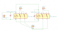
Ah, gotcha. For the +12V in, should the return signal be labeled -12V? Maybe that's where I got things mixed up when I labeled that GND. And then I'll add grounds to the design.

I will be sending the design out, was planning on using https://oshpark.com/
 

levimax

Major Contributor
Joined
Dec 28, 2018
Messages
2,394
Likes
3,522
Location
San Diego
Ah, gotcha. For the +12V in, should the return signal be labeled -12V? Maybe that's where I got things mixed up when I labeled that GND. And then I'll add grounds to the design.

I will be sending the design out, was planning on using https://oshpark.com/
For a very simple project like this you could just use a prototype universal PCB. I have built a similar project and it worked fine on a prototype PCB. With DC on the relays and keeping everything as small as possible and located so leads are as short as possible I just don't see there will be any problems. Even if you want a "real" PCB for on the final version it would not be a bad idea to make a prototype PCB version to confirm everything works and fits like you want. It will only cost a few dollars. In any case have fun.... DIY is a lot of fun.
 

MakeMineVinyl

Major Contributor
Joined
Jun 5, 2020
Messages
3,558
Likes
5,875
Location
Santa Fe, NM
Ah, gotcha. For the +12V in, should the return signal be labeled -12V? Maybe that's where I got things mixed up when I labeled that GND. And then I'll add grounds to the design.

I will be sending the design out, was planning on using https://oshpark.com/
If you mark it -12V, that would imply that it is a negative 12 volts. Use the GND symbol for the signal grounds and tie them to that net. To differentiate the 12V ground, I'd label it "0" so its net doesn't get mixed up with the signal ground nets when you generate the Gerbers.
 
OP
S

starfly

Senior Member
Forum Donor
Joined
Jun 6, 2019
Messages
353
Likes
289
If you mark it -12V, that would imply that it is a negative 12 volts. Use the GND symbol for the signal grounds and tie them to that net. To differentiate the 12V ground, I'd label it "0" so its net doesn't get mixed up with the signal ground nets when you generate the Gerbers.

Is this a better way to draw it? Also added load resistors per Collin's suggestion (though I have no idea what actual part I'd need to get for that), and removed the 2nd diode.

1633052101200.png


Edit: and by the way, I owe all of you a beer for all your help. Really appreciate it, I'm learning a lot!
 

MakeMineVinyl

Major Contributor
Joined
Jun 5, 2020
Messages
3,558
Likes
5,875
Location
Santa Fe, NM
Is this a better way to draw it? Also added load resistors per Collin's suggestion (though I have no idea what actual part I'd need to get for that), and removed the 2nd diode.

View attachment 156458

Edit: and by the way, I owe all of you a beer for all your help. Really appreciate it, I'm learning a lot!
You're still not showing the signal grounds for inputs and outputs. I would keep the load resistors at something like 100K or greater since the inactivated contacts are going to be loading the signal lines for the input which is being used at the time. It is important that you place the grounds since if they are not on the schematic, they are not going to be generated when you make the Gerbers. Each component (even eyelets) must have an associated footprint so the proper holes and silk screen can be generated for each component. I don't know what layout program you are using (I use Altium), but you should get familiar with the protocols for making boards so that it goes smoothly in the future.

This is a very simple audio circuit schematic showing signal grounds.

Untitled-1.jpg
 
Last edited:
Top Bottom