• WANTED: Happy members who like to discuss audio and other topics related to our interest. Desire to learn and share knowledge of science required. There are many reviews of audio hardware and expert members to help answer your questions. Click here to have your audio equipment measured for free!

How to make quasi-anechoic speaker measurements/spinoramas with REW and VituixCAD

fluid

Addicted to Fun and Learning
Joined
Apr 19, 2021
Messages
694
Likes
1,198
I'm not sure I buy that chart at face value.
The previous slide is a worst case scenario prediction based on a perfectly reflective surface and defined distance.

Vituix can be used to reproduce the same thing, a delayed full amplitude copy at 18.6us. If you make the reflected copy lower in amplitude it moves from a deep dip to a ripple.
So if you polish your concrete to a mirror finish you might see something getting closer to it, but there will still be loss which will reduce the effect.

Vituix reflection.png
 

mwmkravchenko

Active Member
Joined
Nov 20, 2018
Messages
185
Likes
199
Location
Perth Ontario
I have a paper by Mark Gander in the late 70's that goes into detail how to take wideband groundplane measurements. (Attached below) And as mentioned the mic's height off of measurement plane is the limiting high frequency factor. A good place to use a 1/4" mic as it will get you pretty much all you will ever need in terms of wide bandwidth frequency measurement.

One further point. You can do this on a piece of plywood on grass. You do not need a full smooth plane. And you do not need a full smooth flat plane. I have done many ground plane measurements including comparative validations of what REW can do in it's smoothing methods. One of my best places is a 50 foot by 100 foot above ground evaporation bed for our septic system. Nice and flat, raised about 4 feet above the surrounding area. I throw down a sheet of 1/2 inch and put the device under test on one end of the plywood tipped about 10 degrees and the mic at 2 metres if I want 1 metre 2Pi equivalent. If it's a column speaker try measuring on it's side and varying the mic placement just like you would do on axis measurements.

Last point. Just like an anechoic chamber measurement,or a groundplane measurement you will be missing floor and ceiling bounce. Or a nearfield measurement as well. So this must be taken into account as you will naturally have a dip between 1 and 4 kilohertz that will be missing some energy. You can calculate that out if you are willing to do the math. Experience will help you there as well.

Mark
 

Attachments

  • Ground Plane Measurements Mark Gander.pdf
    949.2 KB · Views: 135

Jon AA

Senior Member
Forum Donor
Joined
Feb 5, 2020
Messages
468
Likes
910
Location
Seattle Area
Thanks for the Paper! I see it includes the correction I was talking about (at the very end). It looks like the suggestions in the Arta manual were taken directly from it.

The concrete in my shop was polished very, very smooth and sealed. Not quite a mirror surface, but not far off either, so I should be good there.

Back to the HF error we're talking about here: Since it seems to be a smooth, predictable (if you get the math right), magnitude error (no mention of loss of resolution), it should be easy to correct for, no? It's quite easy to get a highly precise gated free field measurement when you only care about high frequencies.

I don't see why one couldn't take a measurement with the speaker off the ground a ways, use that as your baseline for HF, then compare that with your on-axis GP measurement and come up with a correction factor. Sort of an in-situ secondary mic calibration.

The same could be done for the baffle step error that would be caused when one lays the speaker on its side--compare that measurement to the corrected GP measurement when the speaker was standing upright and you can correct for the apparent doubling of the baffle width.

Any holes in that plan?
 

ctrl

Major Contributor
Forum Donor
Joined
Jan 24, 2020
Messages
1,640
Likes
6,281
Location
.de, DE, DEU
Has anybody taken ground plane measurements at around the 5:1 suggested limit (10m for a 2m measurement or 5m for a 1m measurement to the nearest wall) to see the effect that first reflection actually has? Is it large enough to give up better bass resolution by not including it? Even if 1 dB errors occurred (I assume mainly in the bass region?) may that still not be more accurate than nearfield sums and a calculated baffle step (all of which can be prone to errors, time consuming and very difficult to do, depending upon the speaker)?

If I had access to such a hall, I would also experiment with GP measurements :D

You can consider a very rough theoretical worst case for your hall:

When measuring without a gate, there are coherent reflections, especially in the bass range, in a hall with smooth walls.

Depending on the frequency and the phase shift of the reflections compared to the loudspeaker signal at the measurement microphone, in the worst case there can be optimal addition or cancellation of source and reflections.

If we assume that the loudspeaker is located in the center of the room and the distance to the outer walls of the hall is approximately the same (we simply ignore the reflection from the hall floor and ceiling ;)) and let's further assume that the distance to the walls is 8m each and the loudspeaker is measured at a distance of 1m.

Each reflection arriving at the mic has traveled a distance of 8+8m (roughly rounded). The reflection has a -6dB*4 lower sound pressure than the source (loudspeaker) at the measurement microphone. We are only interested in the four first-order reflections from the walls.

If our measurement signal from the loudspeaker arrives at the mic with 90dB, then the reflections arrive with 90 - 6*4 = 66dB.

This results in the worst case that the measured sound level shows instead of 90dB:
realSPL = 20*log(10^(90/20) + 10^(66/20) + 10^(66/20) + 10^(66/20) + 10^(66/20)) = 92dB

Thus, in the worst case, a deviation of +-2dB could occur in the bass range. Therefore a ripple of the measurement with +-2dB amplitude.
The higher the frequency and the greater the proportion of the sound that is reflected diffusely, the smaller the deviation.

Since your new shop has a non-square area, the ripple should not be that large in reality. I could imagine a ripple +-1-1.5dB amplitude as realistic worst case for non gated measurement (with the assumptions from the example - floor and ceiling will add additional, maybe more severe, ripples).
 
Last edited:

mwmkravchenko

Active Member
Joined
Nov 20, 2018
Messages
185
Likes
199
Location
Perth Ontario
Thanks for the Paper! I see it includes the correction I was talking about (at the very end). It looks like the suggestions in the Arta manual were taken directly from it.

The concrete in my shop was polished very, very smooth and sealed. Not quite a mirror surface, but not far off either, so I should be good there.

Back to the HF error we're talking about here: Since it seems to be a smooth, predictable (if you get the math right), magnitude error (no mention of loss of resolution), it should be easy to correct for, no? It's quite easy to get a highly precise gated free field measurement when you only care about high frequencies.

I don't see why one couldn't take a measurement with the speaker off the ground a ways, use that as your baseline for HF, then compare that with your on-axis GP measurement and come up with a correction factor. Sort of an in-situ secondary mic calibration.

The same could be done for the baffle step error that would be caused when one lays the speaker on its side--compare that measurement to the corrected GP measurement when the speaker was standing upright and you can correct for the apparent doubling of the baffle width.

Any holes in that plan?
Um, it will bugger up the possibility of taking an anechoic like measurement of your loudspeaker. Your high frequency limit is literally the reflection off of the floor between the mic and the floor. So if you have a true 1/4" mic you are well up around 20Kilohertz. I use a couple from RST Tech that are really accurate mics.

You can get these off of Alibaba if you are a little adventurous.
 

Attachments

  • RST1000 Measurement Microphone.pdf
    77.1 KB · Views: 88

Newman

Major Contributor
Joined
Jan 6, 2017
Messages
3,554
Likes
4,401
The Mark Gander article says a ½” mic capsule is accurate to over 20 kHz when touching the ground. So just use a standard ECM8000 or UMIK mic.
 

mwmkravchenko

Active Member
Joined
Nov 20, 2018
Messages
185
Likes
199
Location
Perth Ontario
The Mark Gander article says a ½” mic capsule is accurate to over 20 kHz when touching the ground. So just use a standard ECM8000 or UMIK mic.
Yup. I call it insurance. And I presented an example of a great little mic if anyone needs one.

Mark
 

Newman

Major Contributor
Joined
Jan 6, 2017
Messages
3,554
Likes
4,401
It does look sweet, but its SMB connector is not the USB or XLR that I am used to. Not sure how to link it to a computer.
 

mwmkravchenko

Active Member
Joined
Nov 20, 2018
Messages
185
Likes
199
Location
Perth Ontario
It does look sweet, but its SMB connector is not the USB or XLR that I am used to. Not sure how to link it to a computer.
It's a BNC on the end of the cable that I got it with. I did a BNC to XLR and pluged it in. You need to power a mic like this via a microphone pre-amplifier. I use a Umik microphone many times myself. Nothing all that bad about them either.

Mark
 

Jon AA

Senior Member
Forum Donor
Joined
Feb 5, 2020
Messages
468
Likes
910
Location
Seattle Area
If I had access to such a hall, I would also experiment with GP measurements :D
Thanks, that's exactly the type of sanity check I was looking for! You also bring up some new points to ponder.

The shop is 60' wide so when centered I can get roughly 9 meters from each wall and I can get farther from the back wall (74 feet from the back wall to the front "half wall" close to where the pic was taken from). I was originally planning to center the DUT and mic in that end of the building, but your point about the ripples makes me wonder if an offset location so all the reflections happen at different times might help. However, if most of the ripples happen in the deep bass, it may require a large offset to get them to cancel to a meaningful extent and may not be worth it. Certainly something to try and see how it works.

I wasn't actually planning to do the measurements completely without gating, but hoping that instead of cutting it off at ~50 ms, I could extend it to ~95 or ~140 if that first reflection didn't mess things up too much. I figured at some point all the added noise from the reverb (this room has a lot of that!) would add too much noise to the signal that needed to be smoothed out. Then again, maybe my original question would still apply for longer gating if the reverb is so low in level it doesn't change the overall response, maybe having more micro-hashes to smooth out is worth better getting bass resolution. I think I'll just need to try some things and see how they work to answer questions like that.

Obviously the best idea would be to make some DIY absorbing panels. I'm envisioning something like a portable whiteboard you'd find in a classroom, where the teacher can roll it out in front of the class when needed and roll it back into the corner of the room when it's not. Except it would be open on both sides and instead of a whiteboard have a thick layer of rockwool. Those could be rolled out to intercept the first reflections with a healthy air gap between them and the walls. Unless absurdly thick they certainly wouldn't eliminate the reflections from the lowest bass, but they may reduce it considerably. Or maybe just surrounding the measuring area with the panels.... I could end up deep down the rabbit hole! Should be fun though.
 

CleanSound

Major Contributor
Forum Donor
Joined
Apr 30, 2023
Messages
1,654
Likes
2,511
It took Erin from Erin's Audio Corner 12 hours to measure the Revel F226Be, that's before he got a Klippel NFS.

Now I know why.
 

Jeromeof

Addicted to Fun and Learning
Forum Donor
Joined
Jul 25, 2021
Messages
637
Likes
1,035
Location
Ireland
I am thinking of measuring a few mid-range bluetooth speakers (for a bit of fun) - specifically 3 of them -and specifically I want to measure the various pre-shipped DSP options (of at least say 10 different DSP presets per speaker) and I was thinking rather than measuring them in-room (which I have done already for a few of the presets to understand how to EQ them ), would it be beneficial to do a quasi-anechoic measurement i.e. from 200Hz up. The weather is nice and I am out in the back garden already (with no neighbours for the next few days :D ). I would probably do a few combinations of bass boost on/off etc where the speaker's DSP had this capability.

I would probably only measure the on-axis response at for each DSP - otherwise I would be probably be forever lining things up but looking for some advice? What I was wondering:

1. Most of these are stereo speakers though obviously the speakers are close together - so would I just measure a stereo measurement or do a mono measurement?
2. If stereo were best to place the microphone e.g. 1M from centre of the 2 speakers?
3. Any other thing I should check before starting this process (I would be a shame to spend 5-6 hours only to have to redo the measurements because I forgot something obvious)?
4. Is there any accuracy of bass distortion measurements when done this way?

I feel that most bluetooth speakers are moved around all the time and therefore the "room" will always affect the low level, so it is pointless doing any bass measurements - but would the accuracy of doing measurements with no reflections in my back garden be of any benefit compared to just measuring them in one of the rooms in the house?
 

alex-z

Addicted to Fun and Learning
Joined
Feb 19, 2021
Messages
915
Likes
1,698
Location
Canada
I am thinking of measuring a few mid-range bluetooth speakers (for a bit of fun) - specifically 3 of them -and specifically I want to measure the various pre-shipped DSP options (of at least say 10 different DSP presets per speaker) and I was thinking rather than measuring them in-room (which I have done already for a few of the presets to understand how to EQ them ), would it be beneficial to do a quasi-anechoic measurement i.e. from 200Hz up.

Doing only on-axis won't give you a complete picture of speaker performance. If you use those bluetooth speakers indoors, the off-axis performance greatly influences room interaction, which is a major portion of what you hear.

You would measure mono. Measuring in stereo introduces comb filtering that doesn't reflect real world use, and you need mono data if you want to compare against other peoples measurements.

For small speakers, 1 metre mic distance is fine. Point it at the acoustic centre, middle of the drivers unless the manufacturer specifies otherwise.

Take ground plane measurements, you can splice that into the gated measurements to get an idea of each speakers bass extension.

Compression tests are also useful, active speakers tend to change their response with output volume. For this, on-axis data only is fine.

Your distortion data won't be totally accurate, but it will be significantly more accurate than doing in-room sweeps.
 
Last edited:

mwmkravchenko

Active Member
Joined
Nov 20, 2018
Messages
185
Likes
199
Location
Perth Ontario
Doing only on-axis won't give you a complete picture of speaker performance. If you use those bluetooth speakers indoors, the off-axis performance greatly influences room interaction, which is a major portion of what you hear.

You would measure mono. Measuring in stereo introduces comb filtering that doesn't reflect real world use, and you also need mono data if you want to compare against other peoples measurements.

For small speakers, 1 metre mic distance is fine. Point it at the acoustic centre, middle of the drivers unless the manufacturer specifies otherwise.

Take ground plane measurements, you can splice that into the gated measurements to get an idea of each speakers bass extension.

Compression tests are also useful, active speakers tend to change their response with output volume. For this, on-axis data only is fine.

Your distortion data won't be totally accurate, but it will be significantly more accurate than doing in-room sweeps.
You can do wide range groundplane measurements all the way up 10 18khertz with a standard 1/4" mic. Two stones with one bird. And it is an anechoic equivalent. Only caveat is 2 metre distance equals 1 metre 2 pi.
 

dfishon5

New Member
Joined
Oct 21, 2023
Messages
2
Likes
0
I am new at this, and I'm trying to learn vituixCAD and REW. Is there tech support for these programs? How do I get started? I'm retired and this is my hobby and passion.
 

dcibel

Member
Joined
Feb 8, 2021
Messages
47
Likes
52
You should find answers on the websites for the programs...

VituixCAD, start here, you will see "How to start", and link to official support forum:

REW, you will find a forum link on the website for official support location, and help file here:

How to get started? First step is buy a mic and audio interface and start measuring, get some hands on experience. I recommend XLR mic and 2 channel USB audio interface, say no to USB mic. I use a Line Audio Omni1 and a Motu M4 FWIW.

I also recommend downloading latest 5.20.14 "early access" version of REW found on the support forum. It's been early access for a year now without official release, a bit sad TBH but the early access version is stable and includes MANY improvements over 5.20.13.

Have fun!
 

Rick Sykora

Major Contributor
Forum Donor
Joined
Jan 14, 2020
Messages
3,637
Likes
7,389
Location
Stow, Ohio USA
It took Erin from Erin's Audio Corner 12 hours to measure the Revel F226Be, that's before he got a Klippel NFS.

Now I know why.

If you are referring to measuring the speaker below the room transition, this is more work but does not account for 12 hours. It might take that long initially to be confident enough of the full results though. Except for reviewers, designers and DIYers, anyone else should only measure individual speaker performance if they suspect a speaker defect.

For more casual hobbyist, suggest it is easiest to focus on measuring the in-room performance. If wanting to verify the speaker performance above the room transition, can use this thread to do so. Would not spend time trying to figure out nearfield or other methods to measure the bass and integrate it to gated measurements. If you are just trying to ensure consistent bass performance of the speaker(s), nearfield is fine. Otherwise, the in-room bass performance is so much more dependent on all the contributing speakers (and the room) that focusing on a single speaker is not going to help much imo.

My experience has been that some are confused by how measuring a speaker (independent of the room) differs from measuring a set speakers in a room. If one is just trying to measure to get good system performance, they should stick to the basic REW instructions and/or Amir’s tutorials.:)
 
Last edited:

dfishon5

New Member
Joined
Oct 21, 2023
Messages
2
Likes
0
You should find answers on the websites for the programs...

VituixCAD, start here, you will see "How to start", and link to official support forum:

REW, you will find a forum link on the website for official support location, and help file here:

How to get started? First step is buy a mic and audio interface and start measuring, get some hands on experience. I recommend XLR mic and 2 channel USB audio interface, say no to USB mic. I use a Line Audio Omni1 and a Motu M4 FWIW.

I also recommend downloading latest 5.20.14 "early access" version of REW found on the support forum. It's been early access for a year now without official release, a bit sad TBH but the early access version is stable and includes MANY improvements over 5.20.13.

Have fun!
Thank you
 

Sokel

Master Contributor
Joined
Sep 8, 2021
Messages
6,254
Likes
6,383
Trying to simulate some speakers I have here and finding no other way to add the port,I measured it nearfield (very),I did the whole proses,etc and added it as a driver.
Is it right or wrong?Is there another way?

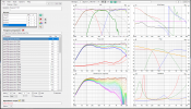
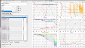
No Port.PNG Port.PNG
 
Top Bottom