• WANTED: Happy members who like to discuss audio and other topics related to our interest. Desire to learn and share knowledge of science required. There are many reviews of audio hardware and expert members to help answer your questions. Click here to have your audio equipment measured for free!

Reverse engineering a crossover

vdH_83

Member
Joined
Dec 7, 2023
Messages
16
Likes
4
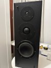
To get a better understanding of speakerdesign I started a quest of chancing a set of Dynaudio speakers. (I have 4 of them) Maybe turning it into an active system.

It is a closed cabinet, 3-way system with Dynaudio components:
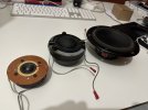
Tweeter: D52-AF
Middome: D21-AF
Woofer: 17W75

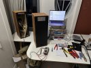
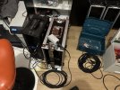
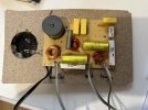
First step is reverse engineering the crossover.

Can somebody identify the components in the crossover, explain which components are in which path and what each component does?

Any help is much appreciated

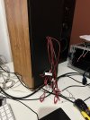
Picture 1: Crossover (glued to the board)
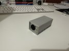
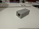
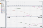
Picture 2: Components measured with smaart Path: DA->Bryston 2B ->XO -> POL-DI -> AD
 

Attachments

  • ASR_1.jpeg
    ASR_1.jpeg
    278.3 KB · Views: 155
  • ASR_2.png
    ASR_2.png
    649.9 KB · Views: 156

terryforsythe

Senior Member
Forum Donor
Joined
May 4, 2022
Messages
489
Likes
513
The coils of wire, as well as the large gray bobbin with wire coiled around it, are inductors. They pass low frequencies and filter high frequencies.

The yellow elements are capacitors. They pass high frequencies and filter low frequencies.

The white elements are resistors. They provide a level of resistance at all frequencies.

I am not sure what is the rectangular gray object that is sitting on top of one of the inductors. Perhaps it is a capacitor, but hard to tell from the picture.

The connections are on the reverse side of the board, so I cannot tell from the picture which components are in which path. I suggest that you trace out the signal paths and draw a schematic of what you find. You probably need an LCR meter to measure the values of the unmarked components.

Here is a link explaining the components and the symbols to use in the schematic: https://science4fun.info/resistors-capacitors-and-inductors/
 
Last edited:

terryforsythe

Senior Member
Forum Donor
Joined
May 4, 2022
Messages
489
Likes
513
One note: Passive crossovers typically do not represent the very best possible design. Instead, they typically are designed to fit within a particular budget, fit within packaging constraints, and keep everything phased properly.

Once you switch to active crossovers, you don't have those constraints - everything is tunable, especially if you use DSP for the crossovers. Once you pay for a proper DSP unit, there is no additional cost to change filter topologies, add parametric equalization and/or adjust time delays for phase alignment. Thus, going active with a suitable DSP unit, you can significantly improve speaker performance over the passively filtered performance (assuming you also have good quality amplifiers and DACs).

Thus, rather than trying to actively replicate the passive crossover, I would start fresh. You can use REW and/or ARTA software to measure the frequency response, impedance and phase characteristics of the individual drivers in the speaker cabinet. Then import those measurements into VituixCAD2 to model various active crossover settings, equalization and time delays for those drivers to achieve a target frequency response for the speaker.
 
Last edited:

MaxwellsEq

Major Contributor
Joined
Aug 18, 2020
Messages
1,754
Likes
2,656
The circuit is created by the traces on the other side of the board. The old fashioned trick is to use tracing paper to draw the traces. Then flip the tracing paper over and draw the components on over this. You can then work out the circuit diagram. But you can't work out the inductance of a coil by looking at it, you will need to measure it.
 
OP
V

vdH_83

Member
Joined
Dec 7, 2023
Messages
16
Likes
4
The coils of wire, as well as the large gray bobbin with wire coiled around it, are inductors. They pass low frequencies and filter high frequencies.

The yellow elements are capacitors. They pass high frequencies and filter low frequencies.

The white elements are resistors. They provide a level of resistance at all frequencies.

I am not sure what is the rectangular gray object that is sitting on top of one of the inductors. Perhaps it is a capacitor, but hard to tell from the picture.

The connections are on the reverse side of the board, so I cannot tell from the picture which components are in which path. I suggest that you trace out the signal paths and draw a schematic of what you find. You probably need an LCR meter to measure the values of the unmarked components.

Here is a link explaining the components and the symbols to use in the schematic: https://science4fun.info/resistors-capacitors-and-inductors/
Great! Lets see if I can get the PCB of the board in one piece, draw a schematic and measure the components!

Thanks alot! Probably posting the result in the next days.
 
OP
V

vdH_83

Member
Joined
Dec 7, 2023
Messages
16
Likes
4
The circuit is created by the traces on the other side of the board. The old fashioned trick is to use tracing paper to draw the traces. Then flip the tracing paper over and draw the components on over this. You can then work out the circuit diagram. But you can't work out the inductance of a coil by looking at it, you will need to measure it.
At first I didnt understand why tracing paper was needed, but now I see the back I get it. Unto the next step: A diagram :)
 
OP
V

vdH_83

Member
Joined
Dec 7, 2023
Messages
16
Likes
4
And here we are. After trying to chip away the wood with a router I tried heating the glue. Which was a winner. The glue turned into syrup when it was heated. Very easy!

After some googling I found out this PCB-layout has been used for many speakers, but with different components.

IMG_6271.jpeg
 

DVDdoug

Major Contributor
Joined
May 27, 2021
Messages
3,035
Likes
4,004
If you are going to go-active, probably all you need to know is the two crossover frequencies.

Analog active filters/crossovers are a lot cheaper & easier to build than digital, but digital is more flexible and tweakable and making a more advanced or more complex crossover is simply a matter of programming (as long as you have enough programming power).

If I was doing it, I'd probably go analog because I could build the circuit board myself. I wouldn't attempt to build a DSP board.

The coils of wire, as well as the large gray bobbin with wire coiled around it, are inductors. They pass low frequencies and filter high frequencies.

The yellow elements are capacitors. They pass high frequencies and filter low frequencies.
That's in series. ;)

In parallel, it's the opposite with a parallel coil blocking/reducing low frequencies and a parallel capacitor blocking/reducing high frequencies. Usually you'll see both series & parallel components. (You can't use them in-parallel alone in this application because low inductive reactance (Ohms) or low capacitive reactance can "short out" the signal from the amplifier. You also need something in series.)

You research "LC" filter to see how high-pass and low-pass filters are made.
 

fpitas

Master Contributor
Forum Donor
Joined
Jul 7, 2022
Messages
9,885
Likes
14,213
Location
Northern Virginia, USA
You research "LC" filter to see how high-pass and low-pass filters are made.
And keep in mind that passive filters are affected by the load presented to them. Simple online calculators cheerfully show you (say) 8 ohms as a load. Unfortunately, few real drivers are a flat, resistive 8 ohms. Getting at the truth requires knowing the complex impedance of the driver vs frequency, and then using a SIM program that takes that into account. Another way is to measure the signal at the driver with the crossover connected, and look for the 3dB and 6dB down points, and maybe take some other points to attempt a guess at the order and Q of the network.
 

radix

Major Contributor
Joined
Aug 1, 2021
Messages
1,409
Likes
1,349
If you google your speakers, like "Dynaudio T330d crossover schematic" you'll likely find someone who's done this already. I don't know what model speaker you have, I just picked one that I know has schematics.
 
OP
V

vdH_83

Member
Joined
Dec 7, 2023
Messages
16
Likes
4
This is what I have so far. I'll double check it tomorrow and turn it into a diagram.
Screenshot 2023-12-15 at 00.06.40.png
IMG_6244.jpeg
 

MAB

Major Contributor
Joined
Nov 15, 2021
Messages
2,153
Likes
4,851
Location
Portland, OR, USA
This is what I have so far. I'll double check it tomorrow and turn it into a diagram.View attachment 334381View attachment 334382
Small but potentially important correction 4.7uF, aka microFarad.
Also, please check this cap to see if really 4.7uF:
1702607453676.png

My eyes are fuzzy!o_O
The resistors
4R7 = 4.7 Ohm
15R = 15 Ohm
10R = 10 Ohm
The yellow caps will have the capacitance written somewhere, perhaps under the glue.
The coils will need to be measured.
Appears to be first order electrical slopes.

By the way, what is the speaker model? This would help too!

Converting to active would be fun. And you may end up with better sound than the 6 dB/octave filters Dynaudio used. In any case, you should start with the driver parameters.

Regarding the drivers, the datasheets are available! And a couple additional slight corrections.
Tweeter Mid-dome: D52-AF
Middome Tweeter: D21-AF
Woofer: 17W75

I would remeasure everything, a microphone and analysis software is your friend. And you might consider using a capacitor on the tweeter either as protection, or as part of the tweeter crossover along with DSP and the tweeter's mechanical rolloff to obtain a target response, like 24dB/octave.

MiniDSP makes 8 channel crossover and DRC:
It can do your stereo 3-way, plus have two channels for subs.
They just released a FlexHTx 8-channel with balanced outputs.
I have built several speakers with MiniDSP crossovers. I like them. There are other options, perhaps not in the same price range.
 

kemmler3D

Major Contributor
Forum Donor
Joined
Aug 25, 2022
Messages
3,358
Likes
6,883
Location
San Francisco
So I am going to second @DVDdoug 's suggestion - you don't have to recreate the crossover if your end goal is to go active.

If you can figure out the crossover frequencies, you can simply measure each driver individually and then design your own crossover from scratch using DSP. That's probably where you will end up anyway, since the original crossover will inevitably have some compromises that you won't need or want to add to the digital xover.

I think it's cool to reverse engineer it for sure, but not necessary.
 
  • Like
Reactions: MAB

Keith_W

Major Contributor
Joined
Jun 26, 2016
Messages
2,661
Likes
6,073
Location
Melbourne, Australia
Many years ago, I converted my passive speakers to active. My plan was to replicate exactly the crossover that came with the speaker in DSP, see if it sounds and measures the same, and then work from there. So like you, I needed to reverse engineer the crossover.

There are 3 ways of doing this. From hardest to easiest:

1. Use REW and send a sine wave sweep through the crossover, and measure the output. Disadvantage: requires additional equipment.

2. Draw out the circuit and get someone who understands circuit design to interpret it for you. There may be software packages or websites that can calculate the outcome of the circuit, but I don't know what they are. This appears to be what you are doing here.

3. Use REW and send a sine wave sweep through the speaker with the crossover intact, and do a nearfield measurement of the driver response. Disadvantage: requires you to be able to separate the connections to individual drivers, which may or may not be difficult. The driver response is mixed in with the crossover, and what you are measuring is a hybrid of the response (i.e. mechanical crossover from the driver + electric crossover). Nevertheless it gives you an idea what the XO freq and slopes are.

In hindsight, I went through a lot of trouble to reverse engineer the crossover, and then I dumped the entire factory crossover design and started over with my own design anyway. It was wasted effort, the only advantage of doing this is so that I can quickly compare what I have now with what the speaker originally sounded like.
 

radix

Major Contributor
Joined
Aug 1, 2021
Messages
1,409
Likes
1,349
2. Draw out the circuit and get someone who understands circuit design to interpret it for you. There may be software packages or websites that can calculate the outcome of the circuit, but I don't know what they are. This appears to be what you are doing here.
Many of the speaker modeling softwares allow you to do a crossover schematic. I use LSPcad, but I think some of the free ones do too. Or you can use any of the spice packages of something like KiCAD. The speaker modeling software would be easiest for a beginner than going to a spice/EE cad package.

I suspect your "throw it out and start from scratch" might be just as good, as long as you can read REW output and detect things like resonances.
 
OP
V

vdH_83

Member
Joined
Dec 7, 2023
Messages
16
Likes
4
Another way is to measure the signal at the driver with the crossover connected, and look for the 3dB and 6dB down points, and maybe take some other points to attempt a guess at the order and Q of the network.
Can this be measured with Smaart, or a system like Dayton dats V3?

I measured the the crossover in 2 ways:

1) With woofer/mid-dome/tweeter connected
2) Without the woofer/mid-dome/tweeter connected.

The outcome was very different. One of the things that stood out was that the crossover didn't filter any high frequencies from the "low path". The cross-over frequencies were also different. See pictures.

Screenshot 2023-12-18 at 21.36.58.png
Screenshot 2023-12-18 at 21.37.18.png
 
OP
V

vdH_83

Member
Joined
Dec 7, 2023
Messages
16
Likes
4
So I am going to second @DVDdoug 's suggestion - you don't have to recreate the crossover if your end goal is to go active.
Thnx, maybe i'll turn it into an active system one day. Main goal is to understand cross-overs and speakers design in general. I work with speakers daily and sometimes I measure things that I can't trace back to an acoustic issue. Although I've read 2 books on speaker design, the best way to learn is to take things apart, rebuild it and learn while you go. At least, that is how it works for me. :)
 
OP
V

vdH_83

Member
Joined
Dec 7, 2023
Messages
16
Likes
4
The schematic:

Does this make any sense?

Can somebody point out in the schematic which components, or group of components are responsible for the actual High-pass and low-pass filtering? I assume that there is also an attenuator (or 2) in the schematic. If so, where is it?

Screenshot 2023-12-18 at 21.31.49.png
Screenshot 2023-12-18 at 22.02.06.png
 
Last edited:
OP
V

vdH_83

Member
Joined
Dec 7, 2023
Messages
16
Likes
4
GENERAL INFO

Brand: Dynaudio
Model: Recital

I have 4 speakers of the same model:

1) Has been taken apart
2) Has been modified to measure the XO on every in- and output. See picture.
3+4) Stay as they are.

On the last 2 pictures you can see the Speaker-DI by "Atelier der Tonkunst". Very helpful! Its a DI that brings speaker-level signals back to line-level. This way it is possible to measure the output of an amp (or a crossover) and compare the input with the output.
 

Attachments

  • Pic_1.jpeg
    Pic_1.jpeg
    143.9 KB · Views: 27
  • Pic_2.jpeg
    Pic_2.jpeg
    248.4 KB · Views: 25
  • Pic_3.jpeg
    Pic_3.jpeg
    291.7 KB · Views: 26
  • Pic_4.jpeg
    Pic_4.jpeg
    301.9 KB · Views: 26
  • Pic_5.jpeg
    Pic_5.jpeg
    231 KB · Views: 26
  • Pic_6.jpeg
    Pic_6.jpeg
    158.5 KB · Views: 27
  • Pic_7.jpeg
    Pic_7.jpeg
    166.2 KB · Views: 28
  • Pic_8.jpeg
    Pic_8.jpeg
    160.9 KB · Views: 25
Top Bottom