What is missing from the LCC's implementation seems to be any kind of filtering. The algorithm seems to be on the web, and it's just feeding decaying copies of the sound between the channels.
Now, I worked with this myself for a bit just over this weekend. Description of the algorithm I came up with is here:
for (size_t n = 0U; n < left_in.size(); n ++) {
auto ao = left_in[n] - decay_gain * b.get_sample();
auto bo = right_in[n] - decay_gain * a.get_sample();
left_out[n] = ao;
right_out[n] = bo;
a.put_sample(ao);
b.put_sample(bo);
}
For those who can't read C++ at all (and it isn't my forte, either), word description follows. You read input audio from left_in and right_in, and write audio to left_out, right_out, using the subscription [n] operator that writes to memory slot for the n'th sample. In actual processing, you ask for left channel input, and subtract the processing unit b (right)'s current sample with a decay gain factor (< 1, to make it quieter). You then do the same with right channel but this time use processing unit a (left). After writing the produced audio, the processing unit a receives the produced audio output sample for left channel, and unit b receives the output sample for the right channel. This achieves the expected infinite recursion where decaying copies of past audio loop across the channels, until they decay to nothing, and they invert during each pass also.
But what is the processing unit doing? Well, get_sample reads a sample from a delay line. If delay line is 15 samples long, the sample returned now was put in 15 samples ago.
float get_sample() {
return data[data_index];
}
My put_sample performs audio filtering for each copy and stores the sample in the end:
void put_sample(float sample) {
sample = f1.process(sample);
sample = f2.process(sample);
sample = f3.process(sample);
sample = f4.process(sample);
sample = f5.process(sample);
data[data_index] = sample;
data_index = (data_index + 1) % data.size();
}
f1-f5 variables are all instances of generic 2nd order biquad filters. These are from the classic audiodsp cookbook.
This is the configuration I have ended up with. It optimizes the response between the HRTF differences for a KEMAR dummy head at 30 degree ipsilateral and contralateral angles.
f1.set_high_pass(300, rate, 0.710); /* frequency, sampling rate, quality */
f2.set_peaking_band(1042, rate, -7.4, 1.798); /* frequency, sampling rate, gain, quality */
f3.set_peaking_band(2221, rate, -6.2, 3.140);
f4.set_low_pass(3000, rate, 1.0); /* same arguments as high pass */
f5.set_peaking_band(3702, rate, -5.4, 3.108);
The delay line should be 313 us long if you work with equilateral triangle, which is what this is designed for because the HRTF data is also for 30 degree angles to left and right. At 48000 Hz sampling rate, 15 samples long delay achieves an almost bang-on match 312.5 us, so that will be the length of delay line in many cases.
I'm reasoning that the red trace is the sensitivity of the ear to the contralateral sound and generally what is left of the sound that made it to other side of the head. The green curve is the ear's sensitivity to sound from the same side. To cancel this sound, I need to produce the filter shape in yellow and apply it, so that it would match with the tonality of the sound hitting the ear as precisely as possible. In reality, this is barely anything more than a bandpass made of a highpass filter at 300 Hz and lowpass at 3000 Hz.
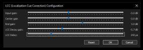
In this implementation, even the decay gain (-2 dB) is a fixed value because it's part of this general filter fit. If you change the overall level of the filter shape, you mess up the cancellation, in theory. The only real user-tunable parameter is the delay, but even that should also always be 313 us if you follow recommended equilateral layout.
Edit addendum: I read all kinds of wild claims on the Internet about what the inter-ear distance is, from 17 cm to 23 cm. I measured mine with tape measure to be about 21 cm apart, but I saw previously 21.5 cm being recommended as this value, so I went with that one. I also see all sorts of really funky claims about what the time of flight difference is between e.g. right ear and the left speaker, and the right ear and the right speaker. I've even seen claims that go pretty low, like < 300 us, which I don't think can be correct.
I performed some geometry to arrive at 313 us, because I need to know when to play the sound that comes from the nearer speaker to account for the travel time difference from the speaker farther away from that ear. For this effect, what I needed to know is not related to what the interaural time delay is for some 30 degree incident angle. It can be something like 200 us for all I care. What I actually need to know is when I send the inverted copy of the audio out from the speaker that is nearer that ear. I think this is different from interaural time delay, but the geometric result should be robust (or at least I can't find any fault in how I reasoned it).
 github.com