Great questions actually. Thank you.
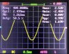
The OPA1622 is able to provide more current with a positive swing than with a negative, so not surprisingly it clips sooner on the negative rail than the positive when forced to current limit. The clipping behaviour is clean, though.
View attachment 99078View attachment 99079
The behaviour with asymmetrical power supply is clean as well. Once you get down to +1.5/-12 V the amp will turn off as its enable signal goes low. I ran it at +2/-12V and +12/-2 V in the plots below. A 9 V battery will provide around 5.5-6 V when fully discharged, so there's plenty of margin there.
View attachment 99080View attachment 99081
The reason the HP-22 provides a larger pop than what you see in the data sheet is because the data sheet figures show the behaviour when the enable line toggles while the power supply remains stable. My graph shows the behaviour when the power supply is turned on and off. I did fiddle quite a bit with the delay on the enable line and what I show was the best performance I could get without getting into elaborate circuit design.
Start-up and shut-down are surprisingly hard things to get right. While at TI I spent quite a while designing a power-on reset circuit for a digital circuit. It's one of those "can't you just use an RC?" types of circuits that ends up being a few weeks spent simulating the circuit over various corner cases (process, voltage, temperature) to ensure that it produces a reliable reset, even on a power glitch or brown-out. Oh, and please fit it in zero area, because it's only active once...
")
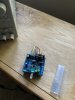
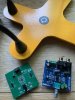
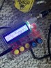
Why two PCBs? Because the OPA1622 is impossible to solder by hand. OK. Maybe not impossible, but darn close. The device measures 3x3 mm and has 14 pads connecting to it underneath. If you have a solder paste stencil, solder paste, and some proficiency using those, you can solder it yourself. I have done the occasional toaster oven reflow (or hot air reflow) for prototypes. But it is not something I would want to support via email. So I leave the hard part to TI.
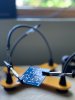
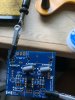
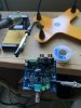
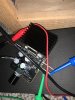
I did consider having the builder remove the 3-pin terminal block from the TI eval board and connecting the two boards by wires, but decided against that. First off, the lead-free solder TI uses is pretty hard to work with. The EVM is a through-plated board (four layers, I think, possibly two) and if you don't have the ability to heat up all three terminals at once, it's pretty hard to get that connector off. And good luck supporting that by email when someone pulls the through-plating out with the connector. Secondly, the footprint required for the wires would interfere with the RCA connectors. I really like the compact nature of this amp and didn't want the 'shield' to become too big. It's really no big deal to connect two wires to one of the terminal blocks. I use 20 AWG wire. It fits just fine.
I don't have a standard enclosure in mind. I'll leave that as an exercise for the reader. I'm sure Hammond has something that'll work. I'll probably search a bit and see if I can find something that'll fit. I will provide a drill template so you can at least get the holes in the right locations.
Tom