Wide range supplies are common for low power devices as their disadvantage is that you have to dimension all the components for the worst case voltage and current. Past 70/100W you use a doubler circuit.

-
WANTED: Happy members who like to discuss audio and other topics related to our interest. Desire to learn and share knowledge of science required. There are many reviews of audio hardware and expert members to help answer your questions. Click here to have your audio equipment measured for free!
You are using an out of date browser. It may not display this or other websites correctly.
You should upgrade or use an alternative browser.
You should upgrade or use an alternative browser.
Millivolt Meter Recommendation for Audio
- Thread starter watchnerd
- Start date
Anyways the modern way is to use a switching regulator that can operate from 110VAC to 220VAC, which is the IC in your circuit I think.
Bridge rectifier -> 400V caps -> TNY178PN - didn't check the datasheet.
Bridge rectifier -> 400V caps -> TNY178PN - didn't check the datasheet.
OP
watchnerd
Grand Contributor
- Thread Starter
- #884
Getting back to the topic, I hooked up an iFi DAC and let it run for a few hours. Ever a source of surprising behaviours, it did not fail to deliver:
View attachment 83775
Heh....
Was it actively playing something?
1 kHz sine wave.Heh....
Was it actively playing something?
OP
watchnerd
Grand Contributor
- Thread Starter
- #886
Wowowow. Is that a console model or the vertically oriented model?
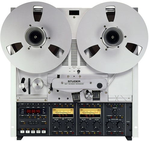
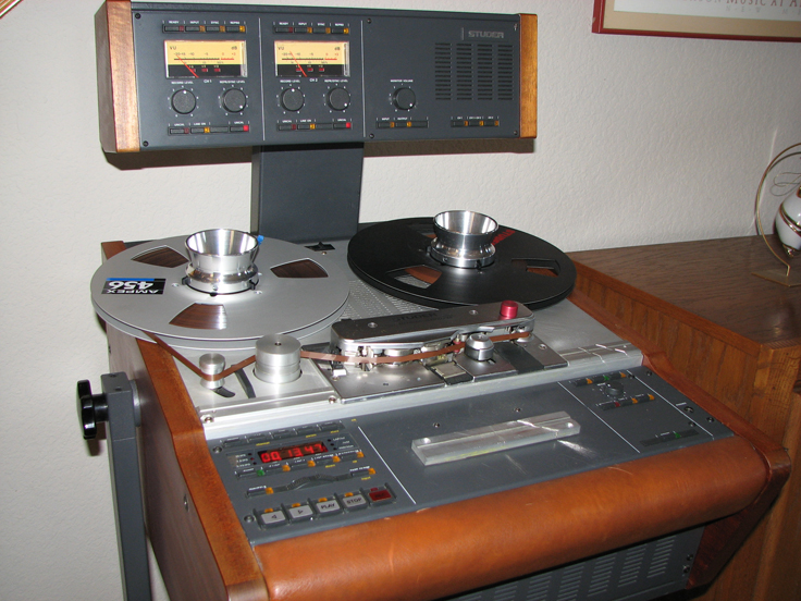
It has arrived.
Separate thread for the A807:
https://www.audiosciencereview.com/forum/index.php?threads/new-studer-a807.16089/
Maybe some thermal thingy going on?
OP
watchnerd
Grand Contributor
- Thread Starter
- #889
OK.....so what is the output voltage of your Revox when playing the 1kHz zero reference tone? I'm taking bets on how close it is before tweaking it.
So I'm not sure what to make of these results.
First, a DC battery test with a D cell battery. The packaging says 1.5V; I have no idea how loose D cell battery tolerances are.
6.7% off spec. Is it the meter or the battery? No idea...
Moving on the to the calibration tape.
The default reference fluxivity for the PR99 MK II is 250 nWB/m = 0 VU
So it's expected that a 355 nWb/m tape gives this result for a 1 kHz tone.
Looks like the left channel is about 0.5 dB too low.
When measuring the 1 kHz test tone at 355 nWb/m = +3 VU, we get this output at the XLR line out jacks, in CAL (calibrated / fixed) mode:
So the next part is where my math is making me less than confident.
At 0 VU on the meter, the output should be +4 dBU at the XLR jacks, which = 1.23 VAC, I think.
So +3 dB on the VU meter should be.....+7 dBU, which = 2.24 VAC??
Is that math correct?
If so, either the output is a little hot, the meter is off by .01V, or my measuring is doing something wrong.
Or my math is wrong.
MakeMineVinyl
Major Contributor
I don't know if your machine has a VU meter calibration adjustment. If it does, you need to get your meters to equal 1.23V at "0 VU". After that, adjust the playback gain so that the meters read +3 if you want 250nWb operating level or zero if you want +6. At any rate, I always thought a "D" cell was 1.56VDC, but that was back in the days of old skool Ray-O-Vac batteries.
For a new 1.5V battery they will measure a little higher like you see there. The resistance across the battery should be low and as it discharges the resistance will increase.First, a DC battery test with a D cell battery. The packaging says 1.5V; I have no idea how loose D cell battery tolerances are.
OP
watchnerd
Grand Contributor
- Thread Starter
- #892
I don't know if your machine has a VU meter calibration adjustment. If it does, you need to get your meters to equal 1.23V at "0 VU". After that, adjust the playback gain so that the meters read +3 if you want 250nWb operating level or zero if you want +6. At any rate, I always thought a "D" cell was 1.56VDC, but that was back in the days of old skool Ray-O-Vac batteries.
It does have VU calibration.
And it is currently reading +3 on a 355 nWB tape = 0 VU @ 250 nWB (more or less).
I think, given the tape is pegging at +3 dB on the VU meter, the current VAC reading at the line-out is about right, based on conversion math.
Looks good at 1.6V for a new non-rechargeable.It's fresh from the package. Probably sitting in a drawer for a year.
MakeMineVinyl
Major Contributor
Inject a 1kHz sine wave into the line input and adjust the voltage until the line output voltage of the machine is 1.23 VAC (don't use the calibration tape for this). Then adjust the meter calibration for 0VU on the internal VU meters. From then on, 0VU will equal 1.23V. After that, you can throw away your multi-meter.It does have VU calibration.
And it is currently reading +3 on a 355 nWB tape = 0 VU @ 250 nWB (more or less).
I think, given the tape is pegging at +3 dB on the VU meter, the current VAC reading at the line-out is about right, based on conversion math.
Last edited:
OP
watchnerd
Grand Contributor
- Thread Starter
- #896
Inject a 1kHz sine wave into the line input and adjust the voltage until the line output voltage of the machine is 1.23 VAC (don't use the calibration tape for this). Then adjust the meter calibration for 0VU on the internal VU meters. From then on, 0VU will equal 1.23V. After that, you can throw away your multi-meter.
What voltage peak to peak from the signal generator?
MakeMineVinyl
Major Contributor
It doesn't matter. Just output any level and adjust the record input level until you get 1.23V from both line outs of the machine. Then adjust the VU meter calibration pots so that they are at "0". Unless your machine is very weird, this should work. Then you can proceed with calibrating playback level using your tape. You don't need your multi-meter after getting your VU meters to read "0" at 1.23V from the line outs.What voltage peak to peak from the signal generator?
My Ampex machine is easy this way; there's no way to adjust the VU meters, so thay must be dead accurate.
Last edited:
OP
watchnerd
Grand Contributor
- Thread Starter
- #898
It doesn't matter. Just output any level and adjust the record input level until you get 1.23V from the line outs of the machine. Then adjust the VU meter calibration pots so that they are at "0". Unless your machine is very weird, this should work. Then you can proceed with calibrating playback level using your tape.
Well, it's weird.
See post #869.
You're supposed to do that step before you mess with the VU meters.
You adjust internal trim pots (not the external ones for the VU meters) and measure at the monitor out, not the line out.
MakeMineVinyl
Major Contributor
Try it the way I described. The manual might want to do another way, but the bottom line is that you want the VU meters to read "0" when the line outs are putting out 1.23V. I guess I'm like the car mechanic who has tuned 76,000,000 engines by feel - don't need no fucking manuals.
restorer-john
Grand Contributor
Well, it's weird.
See post #869.
You're supposed to do that step before you mess with the VU meters.
You adjust internal trim pots (not the external ones for the VU meters) and measure at the monitor out, not the line out.
You are 100% correct. Input levels, playback levels and final stage levels are all adjusted before messing with any VU trims.
Similar threads
- Replies
- 22
- Views
- 2K
- Replies
- 8
- Views
- 1K
- Replies
- 12
- Views
- 1K
- Poll
- Replies
- 49
- Views
- 16K