• WANTED: Happy members who like to discuss audio and other topics related to our interest. Desire to learn and share knowledge of science required. There are many reviews of audio hardware and expert members to help answer your questions. Click here to have your audio equipment measured for free!

What’s Your Triangle in Stereo Speaker Listening?

Which triangle is your stereo speaker setup?


  • Total voters
    176
J J has assigned us some homework, and I am not going to reap the full benefits without doing the homework. I hope, by not ignoring his suggestions, I can also encourage J J to keep educating us. I am also aware that some members here are not familiar with the math, and hopefully this may help them too.
...
And here are the differences in the FR magnitudes between the phantom center and real center, displaying the phantom center dip J J mentioned.
View attachment 393949
Thank you! This looks to me remarkably like an unsmoothed version of the so-called Shirley curve or dip (Shirley, B.G., Kendrick, P., and Churchill, C. (2007). “The Effect of Stereo Crosstalk on Intelligibility: Comparison of a Phantom Stereo Image and a Central Loudspeaker Source,” J. Audio Eng. Soc., 55, pp. 852–863), also I mentioned here https://www.audiosciencereview.com/...nd-speaker-reviews.51091/page-18#post-1845124, but I'll reproduce here (sorry!):
Screenshot 2024-09-21 at 10.33.10 PM.png

You get an A+ in my book. Very nicely done. Notice how that "dip" is smack in the ITD range, too, as well as the floor-bounce range. This is part of why the distance cues get squashed in a 2-channel setting.

Also notice that there are effectively two peaks in the "phantom center" HRIR sum, and that's part of what mucks up the senses of distance, as well, since it's in the "envelope sensitivity" area.
@j_j Could you please explain why this floor-bounce range as per Klippel measurements and what you mentioned is different from what I thought was traditional audiophile understanding of bass frequencies below, say, 200-400 Hz being affected by destructive interference by the first floor reflection in typical listening rooms with typical speaker and listener heights?

Also, @NTK 's graph shows a much higher peak around 8 kHz. Could that in the context of so-called Blauert bands at least partly explain why phantom center images seem to be typically perceived as elevated in the vertical plane (my perception, also Choisel, S., and Wickelmaier, F. (2007). “Evaluation of Multichannel Reproduced Sound: Scaling Auditory Attributes Underlying Listener Preferences,” J. Acoust. Soc. Am., 121, pp. 388–400.)

Thanks!
 
Thank you! This looks to me remarkably like an unsmoothed version of the so-called Shirley curve or dip (Shirley, B.G., Kendrick, P., and Churchill, C. (2007). “The Effect of Stereo Crosstalk on Intelligibility: Comparison of a Phantom Stereo Image and a Central Loudspeaker Source,” J. Audio Eng. Soc., 55, pp. 852–863), also I mentioned here https://www.audiosciencereview.com/...nd-speaker-reviews.51091/page-18#post-1845124, but I'll reproduce here (sorry!): View attachment 393979

@j_j Could you please explain why this floor-bounce range as per Klippel measurements and what you mentioned is different from what I thought was traditional audiophile understanding of bass frequencies below, say, 200-400 Hz being affected by destructive interference by the first floor reflection in typical listening rooms with typical speaker and listener heights?

Also, @NTK 's graph shows a much higher peak around 8 kHz. Could that in the context of so-called Blauert bands at least partly explain why phantom center images seem to be typically perceived as elevated in the vertical plane (my perception, also Choisel, S., and Wickelmaier, F. (2007). “Evaluation of Multichannel Reproduced Sound: Scaling Auditory Attributes Underlying Listener Preferences,” J. Acoust. Soc. Am., 121, pp. 388–400.)

Thanks!
Well, it should look like the Shirley curve :), although I have some doubts about too much smoothing going on.

If you consider direct path only, look at the time difference between two points, say 1 meter above the floor, and say 4 meters (this can vary, of course), and look at the resulting change in shape. There's also the time domain confusion if you look at the phantoms stereo HRIR, that makes the actual time delay rather more ambiguous.

As to elevation, that's somewhat personally variable among listeners, but it certainly can provide various elevation cues.
 
Advancing to post #130. These are the phase response plots processed as described (as far as I understood) in the post. The Python Jupyter notebook is attached.
Hi NTK. Thanks for share graphs and plots processed.
Can you extend the display area of the phase plot to the low frequency area?
 
... traditional audiophile understanding of bass frequencies below, say, 200-400 Hz being affected by destructive interference by the first floor reflection in typical listening rooms with typical speaker and listener heights?

Hi,
The audiophiles might have never done trigonometry and found out that on typical listening heights floor reflection has usually the shortest early reflection path amongst all six we would have in a cubicle room. This means it is usually quite high in frequency. Assuming speakers and listener are setup in an audiophile way, away from the walls all other boundaries make interference lower in frequency than the floor bounce.

Floor bounce might be the most significant though, as floors are often rigid concrete unlike ceilings, which could be less so, and one might have acoustic treatment on most boundaries except on the floor. After all floor bounce has shortest path length it would be loudest of the bunch anyway. Due to small angle toward the specular reflection directivity doesn't usually attenuate this at all. These make it significant, but it is not on low frequency, due to short path length. Heavy dip on mids is usually combination of multiple of these reflections piling up close to each other making one wide dip. Low frequency dips should not be associated with floor reflection in this sense, as it's likely due to some other reflection, or rather combination of many.

edit.
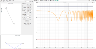
Anyone interested in this stuff can very quickly experiment this in VituixCAD, just make wire connection from source to driver as the program opens up. Then hit the room tab and adjust away. The graph one should look at is the in-room response in Power & DI chart. Here 1m listening height and source height, 3m distance and it's in your bracket. If listening distance was further or driver closer to floor this would go up.
1726988471672.png

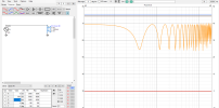
This stuff is relatively fast to test in VituixCAD room tab. Distance to the boundaries is relative to listening height, so to lower a source compared to listening height one must adjust y-coordinate on the driver. Here dropped the ideal point source to 70cm from floor: listening axis is still 100cm from floor and driver is -30cm relative to that.
1726988780368.png
 
Last edited:
The audiophiles might have never done trigonometry and found out that on typical listening heights floor reflection has usually the shortest early reflection path amongst all six we would have in a cubicle room. This means it is usually quite high in frequency. Assuming speakers and listener are setup in an audiophile way, away from the walls all other boundaries make interference lower in frequency than the floor bounce.

Floor bounce might be the most significant though, as floors are often rigid concrete unlike ceilings, which could be less so, and one might have acoustic treatment on most boundaries except on the floor. After all floor bounce has shortest path length it would be loudest of the bunch anyway. Due to small angle toward the specular reflection directivity doesn't usually attenuate this at all. These make it significant, but it is not on low frequency, due to short path length. Heavy dip on mids is usually combination of multiple of these reflections piling up close to each other making one wide dip. Low frequency dips should not be associated with floor reflection in this sense, as it's likely due to some other reflection, or rather combination of many.
...
Anyone interested in this stuff can very quickly experiment this in VituixCAD, just make wire connection from source to driver as the program opens up. Then hit the room tab and adjust away. The graph one should look at is the in-room response in Power & DI chart. Here 1m listening height and source height, 3m distance and it's in your bracket. If listening distance was further or driver closer to floor this would go up.
Oops, I should have written "in the range of," instead of "below" the 200-400 Hz frequency range! Thanks for illustrating (the Q/width of the first or lowest dip might further contribute to its effect). Perhaps erroneously, I tend think of this as in the transition zone of specular vs modal, also this range is often reproduced by woofers or bass drivers. It's also a relatively predictable effect (ceiling reflection would presumably be next, but ceiling heights tend to vary more than loudspeaker driver elevation with respect to typical listening positions), also not in the way that occurs in typical concert hall acoustics (https://www.audiosciencereview.com/...cert-hall-acoustics-links-and-excerpts.51487/)

My question still stands, however--Klippel seems to measure the inferior vertical interference dip as "floor bounce" (https://www.audiosciencereview.com/forum/index.php?threads/revel-f228be-review-speaker.23659/), whereas your examples and https://dtmblabber.blogspot.com/2010/12/little-more-into-boundary-conditions.html, https://www.stereophile.com/content/rbh-641-se-loudspeaker-measurements-part-2 suggest a different frequency range for said "floor bounce." How to reconcile the two?
 
Hi NTK. Thanks for share graphs and plots processed
Can you extend the display area of the phase plot to the low frequency area?
I plotted the phase response using a linear frequency scale so that the best fit straight lines to calculate the delays showed better. Unfortunately the HRTF IR's from the MIT database are only 512 samples long, which means the frequency resolution is only 86 Hz (= Fs/n_sample = 44100/512). Below is the replotted phase response using a log frequency scale (the delay lines from the linear fits are no longer straight lines).
fr_phase.png
 
Hi,
The audiophiles might have never done trigonometry and found out that on typical listening heights floor reflection has usually the shortest early reflection path amongst all six we would have in a cubicle room. This means it is usually quite high in frequency. Assuming speakers and listener are setup in an audiophile way, away from the walls all other boundaries make interference lower in frequency than the floor bounce.

Floor bounce might be the most significant though, as floors are often rigid concrete unlike ceilings, which could be less so, and one might have acoustic treatment on most boundaries except on the floor. After all floor bounce has shortest path length it would be loudest of the bunch anyway. Due to small angle toward the specular reflection directivity doesn't usually attenuate this at all. These make it significant, but it is not on low frequency, due to short path length. Heavy dip on mids is usually combination of multiple of these reflections piling up close to each other making one wide dip. Low frequency dips should not be associated with floor reflection in this sense, as it's likely due to some other reflection, or rather combination of many.

edit.
Anyone interested in this stuff can very quickly experiment this in VituixCAD, just make wire connection from source to driver as the program opens up. Then hit the room tab and adjust away. The graph one should look at is the in-room response in Power & DI chart. Here 1m listening height and source height, 3m distance and it's in your bracket. If listening distance was further or driver closer to floor this would go up.
View attachment 393992

This stuff is relatively fast to test in VituixCAD room tab. Distance to the boundaries is relative to listening height, so to lower a source compared to listening height one must adjust y-coordinate on the driver. Here dropped the ideal point source to 70cm from floor: listening axis is still 100cm from floor and driver is -30cm relative to that.
View attachment 393994

In my case, the floor bounce can't be seen in the measurements from the listening position as it's obstructed by the sofa. My listening triangle is fairly small with a short distance of just about 2 meters to the speakers, and with the curved sofa I have I can't see the speaker drivers in a mirror placed on the floor at the first reflection point.

So there are possibilities to avoid the first reflection from the floor. In many mastering studios, the desk is sometimes strategically positioned to obstruct the floor bounce. In homes, a desk can be used for the same reason as long as it doesn't add a reflected surface on its own, but that can many times be avoided with the right choice of table and distance.
 
PHASE SHIFT IS TIME DELAY.
Hi, with huge respect, knowing you've forgotten more about audio than I've learned :).....

I've found it extremely helpful consider phase as being distinctly different than time.
For me, time is a constant, and independent of frequency;
whereas phase is a cyclic alignment among frequencies, making it frequency dependent.
Only time can fully accurately offset time, and only phase can do the same for phase.

That understanding, has greatly aided my multi-way DIY speaker building, and setting up active multi-way processing.
Mixing up time and phase while tuning, continually proves to be a kludge, ime. Separate them and viola!

I see so many speaker builders mixing up time time and phase, thinking they are substitute's for each other, I wish the idea that they are equivalents would get buried (deep) somehow.

(Realize you have been speaking about phase as it relates to hearing/ITD, etc. Sorry if this post is too misdirected)
 
In my case, the floor bounce can't be seen in the measurements from the listening position as it's obstructed by the sofa. My listening triangle is fairly small with a short distance of just about 2 meters to the speakers, and with the curved sofa I have I can't see the speaker drivers in a mirror placed on the floor at the first reflection point.

That's actually a good thing. It means you don't get an extra false cue from your room.
 
Only time can fully accurately offset time, and only phase can do the same for phase.

Mathematically phase and time are precisely related. phase (in radians) = 2 pi F (in hz) T (in seconds). They are precisely related. Now, compensating for time can mean "moving a driver", meaning it's easier to fix some issues in the time domain, and others in the pure, delay-removed phase domain.

But they are exactly related.
 
In my case, the floor bounce can't be seen in the measurements from the listening position as it's obstructed by the sofa. My listening triangle is fairly small with a short distance of just about 2 meters to the speakers, and with the curved sofa I have I can't see the speaker drivers in a mirror placed on the floor at the first reflection point.

So there are possibilities to avoid the first reflection from the floor. In many mastering studios, the desk is sometimes strategically positioned to obstruct the floor bounce. In homes, a desk can be used for the same reason as long as it doesn't add a reflected surface on its own, but that can many times be avoided with the right choice of table and distance.

Agree it’s often ignored. Your setup looks effective.

Our listening space is in a loft with Japanese tatami floor (not unlike large absorber panels) over traditional gapped timber planks (somewhat transparent to bass). The currently deployed seating is traditional cotton futon on perforated latex, suspended on timber slats and extending bed-like over much of the floor within the listening triangle. Floor bounce takes a beating, either directly via the futon, or the floor underneath.

Screenshot 2023-06-11 at 2.42.26 pm.png

Rough cross-section during initial setup, must try another version with the furniture and better dimensional accuracy (and yes, LP is slightly cantilevered over the void). Floor bounce is first in (or would be, if it made it all the way).
 
Mathematically phase and time are precisely related. phase (in radians) = 2 pi F (in hz) T (in seconds). They are precisely related. Now, compensating for time can mean "moving a driver", meaning it's easier to fix some issues in the time domain, and others in the pure, delay-removed phase domain.

But they are exactly related.
Sure, an easy exact relationship. But the exact time to phase value, holds only for the specified frequency.

All I'm saying is compensate fixed time issues which are not frequency dependent, like acoustic offsets, with fixed time
And compensate phase issues which are frequency dependent with phase offsets, like all-pass or inverse all-pass.

I see too many people try to substitute one for the other when setting up speaker time and phase alignments.... apparently thinking phase can equal fixed time, or vice versa.
On this we agree entirely.
 
Agree it’s often ignored. Your setup looks effective.

Our listening space is in a loft with Japanese tatami floor (not unlike large absorber panels) over traditional gapped timber planks (somewhat transparent to bass). The currently deployed seating is traditional cotton futon on perforated latex, suspended on timber slats and extending bed-like over much of the floor within the listening triangle. Floor bounce takes a beating, either directly via the futon, or the floor underneath.

View attachment 394447
Rough cross-section during initial setup, must try another version with the furniture and better dimensional accuracy (and yes, LP is slightly cantilevered over the void). Floor bounce is first in (or would be, if it made it all the way).

Interesting with the Japanese tatami floor, are those tiles more absorbing than say a thick shaggy rug?
 
Interesting with the Japanese tatami floor, are those tiles more absorbing than say a thick shaggy rug?

I haven't found measurements, one day I may try something myself. I'd expect the absorption curve would be somewhat different to a thick rug (but I think of such rugs as unappealing matrices of fibre and debris, so not a personal option). I'd guess tatami would have more reflection of treble, but be more transparent to bass (to some degree)

Tatami are fairly dense (a thin woven reed mat covers tightly bound rice straw compressed to 50 mm). But I've no idea what the airflow resistivity might be. I modelled them as slotted absorbers, roughly approximating the physical characteristics of the layers (including gapped plank floor and airspace underneath) with resistivity at 50,000 (it could be 10x that, who knows). And the model is outside normal parameters so just a bit of fun really. I couldn't specify the top surface reed mat very accurately so I doubt the mid-treble absorption is as high as indicated, for example. And the bottom air layer is unconstrained, so won't resonate the same way, etc.

Screenshot 2024-09-24 at 5.33.09 PM.png

Screenshot 2024-09-24 at 5.32.34 PM.png

Screenshot 2024-09-24 at 5.33.28 PM.png
 
Last edited:
Back
Top Bottom