Then there has to be some mistake in your setup of the DAC/interface or REW.
In your described scenario with internal loopback you'll get just sole clock source in the system, the J test should be perfect.
With regards to observed skirting, try to check whether you don't have enabled option "Treat 32-bit data as 24-bit" at soundcard options pane. ADI-2 Pro via its USB interface supports full 32-bit audio I/O (eg. the last 8 bits in the word aren't zeroed).
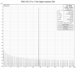
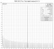
For the reference, here's my loopback via ADI-2 USB in/out and enabled internal loopback. Both 44100 and 96000 is perfect, as expected. I've switched to linear X scale in REW, so you can see, the dominant frequency is exactly in the middle of spectrum (the 1/4 of sampling rate).
If you'd use SPDIF or AES for I/O, then FFT should look similar just with higher noisefloor naturally, as it is 24bit.
Michal

") . It looks good to me.
. It looks good to me.