• WANTED: Happy members who like to discuss audio and other topics related to our interest. Desire to learn and share knowledge of science required. There are many reviews of audio hardware and expert members to help answer your questions. Click here to have your audio equipment measured for free!

Preamp for class d board

OP
Wheely

Wheely

Member
Joined
Feb 8, 2023
Messages
39
Likes
3
Location
B.C
Something like these I figured would do the trick, I see they are rated at 20ma current themselves anyway.
 

antcollinet

Master Contributor
Forum Donor
Joined
Sep 4, 2021
Messages
7,849
Likes
13,270
Location
UK/Cheshire
Ah - ok

They just have the resistor added in the wiring (you can see the bulge under the heatshrink). Resistor preselected for the various voltages.

So - if your signal output can deliver 20mA, and you can find the voltage output, then these will work. Contact the supplier of the amp - see if they can help. If they can provide circuit diagrams, so much the better.
 
OP
Wheely

Wheely

Member
Joined
Feb 8, 2023
Messages
39
Likes
3
Location
B.C
oh I see. I noticed the bulge in these bulbs but didnt put it all together. but as far as getting a diagram for the amp, good luck. cant find much of any info on these boards. seems like this one is fairly new also. Only info on it was that it tested good in Micheal Beeny's video. He says it has good sound quality, its powerful, quiet when you put your ear to the speaker, & that it puts out impressive numbers. Except it didnt perform quite as well under 4 ohm loads. & it doesnt get hot at all even with a heavy load so it will probably last a long time.
 
Last edited:
OP
Wheely

Wheely

Member
Joined
Feb 8, 2023
Messages
39
Likes
3
Location
B.C
Ah - ok

They just have the resistor added in the wiring (you can see the bulge under the heatshrink). Resistor preselected for the various voltages.

So - if your signal output can deliver 20mA, and you can find the voltage output, then these will work. Contact the supplier of the amp - see if they can help. If they can provide circuit diagrams, so much the better.
I was just thinking, maybe the mute/standby light circuit is right within the chip itself? maybe you can identify something on the pins of the tpa3255 chip itself if you check the data sheet ? it is to be believed this amp is containing authentic texas instruments tpa3255 chips
 
OP
Wheely

Wheely

Member
Joined
Feb 8, 2023
Messages
39
Likes
3
Location
B.C
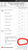
There it is right there. minimum and maximum voltages. so the 3 volt id say. but maybe even 5volt would work perfect I assume. there it is.
 

Attachments

  • Screenshot_20230409-190902.png
    Screenshot_20230409-190902.png
    568.8 KB · Views: 39
OP
Wheely

Wheely

Member
Joined
Feb 8, 2023
Messages
39
Likes
3
Location
B.C
There it is right there. minimum and maximum voltages. so the 3 volt id say. but maybe even 5volt would work perfect I assume. there it is.


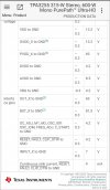
hold on, could it be the 9mA rating here at the bottom instead actually? continuous sink current.
 

Attachments

  • Screenshot_20230409-212537.jpg
    Screenshot_20230409-212537.jpg
    144.8 KB · Views: 31
Last edited:

antcollinet

Master Contributor
Forum Donor
Joined
Sep 4, 2021
Messages
7,849
Likes
13,270
Location
UK/Cheshire
That table you are looking at is "absolute maximum ratings". These are not operating conditions, these are conditions that if you exceed, you will break the device. I guess that the operating voltage is the normal 3.3V logic level - and if I were using it I would only go to half that max rated current of 9mA.

You can also see that the output is "open drain". That means it is just the pin of a transistor. It doesn't supply any voltage at all, it operates like a switch, connecting the contact to ground or not - so you would have to supply the voltage yourself - via whatever current limiting circuit you need. Bear in mind that, according to the datasheet, this output is intended for giving status information to a microcontroller - not for driving an LED - so it is very low current.

I would very much hope that the pin of the IC is NOT connected directly to the terminals of your board as that is a big risk for damaging the device. I would expect at least a transistor buffer between the pin and the output - something that can handle a bit of abuse. However, if your supplier can't give you any information (how is that - surely they must be able to document what the terminals on the board provide you with), the only way will be for you to trace the circuit on the PCB.
 
OP
Wheely

Wheely

Member
Joined
Feb 8, 2023
Messages
39
Likes
3
Location
B.C
Ok, so maybe we can get 2 or 3 electrical engineers together to figure out what bulb I should select to connect to the fault signal
 
Last edited:

antcollinet

Master Contributor
Forum Donor
Joined
Sep 4, 2021
Messages
7,849
Likes
13,270
Location
UK/Cheshire
Ok, so maybe we can get 2 or 3 electrical engineers together to figure out what bulb I should select to connect to the fault signal
no-one can figure that out if they don't know what circuit is on the board.

Is it connected directly to the chip? Or is there a circuit between the chip and the terminals. If the latter, what is the circuit.

We can guess - but if we guess wrong we risk breaking the board.
 
OP
Wheely

Wheely

Member
Joined
Feb 8, 2023
Messages
39
Likes
3
Location
B.C
no-one can figure that out if they don't know what circuit is on the board.

Is it connected directly to the chip? Or is there a circuit between the chip and the terminals. If the latter, what is the circuit.

We can guess - but if we guess wrong we risk breaking the board.
ok. I suppose I could try and trace it. it looks like a pretty basic board. but im not sure you can see anything looking at the board itself. perhaps you would need a actual diagram. thank you for the help by the way,
 
Last edited:
OP
Wheely

Wheely

Member
Joined
Feb 8, 2023
Messages
39
Likes
3
Location
B.C
So I was reading some stuff and a guy who has the same amp asked the seller what that mute output is for & they said you hook up a switch to it
 
OP
Wheely

Wheely

Member
Joined
Feb 8, 2023
Messages
39
Likes
3
Location
B.C
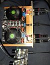
little bit of progress. works good so far
 

Attachments

  • 20230424_211509.jpg
    20230424_211509.jpg
    473.4 KB · Views: 39
OP
Wheely

Wheely

Member
Joined
Feb 8, 2023
Messages
39
Likes
3
Location
B.C
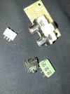
Want to attach this rca/aux input to the amp. Im not sure if it will work properly, or be officially 'hifi' or not.

still waiting on a soldering gun and some 60/40 solder. hopefully I can get it to work good.
 

Attachments

  • 20230421_192226.jpg
    20230421_192226.jpg
    474.2 KB · Views: 30
Last edited:
OP
Wheely

Wheely

Member
Joined
Feb 8, 2023
Messages
39
Likes
3
Location
B.C
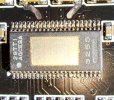
Bad news guys. I went to use the amp the other day, I hooked it up all nicely. right away I found that the right channel was dead. everything was hooked up perfect so I had a hunch right away there was an issue with one chip on the board. Sure enough I pop the fan off and there is a thread of copper shorting out at least 3 or 4 pins on the chip. The copper thread was lodged in the thermal paste. I had a hunch that could happen but never imagined it would happen so easily. rookie mistake

So I have another ordered. Im pretty bummed out. It did look like it could maybe be a real chip at least anyway. ill post a photo of one with the paste cleaned off
 
OP
Wheely

Wheely

Member
Joined
Feb 8, 2023
Messages
39
Likes
3
Location
B.C
authentic?
 

Attachments

  • 20230427_143011.jpg
    20230427_143011.jpg
    999.3 KB · Views: 34
OP
Wheely

Wheely

Member
Joined
Feb 8, 2023
Messages
39
Likes
3
Location
B.C
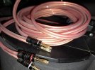
check out the sweet audio cables I threw together using 800 core wire, its about 1cm wide.I used black audiocrast banana plugs

I am pretty happy about these. It is supposed to be oxygen free copper, 800 core hifi wire. 5 meter length of it for $24 cad. I built up a pair of these & it cost me about $65 cad, excellent deal in my opinion
 

Attachments

  • 20230511_210433.jpg
    20230511_210433.jpg
    298.4 KB · Views: 35
Top Bottom