Dear ASR Community,
i want to show you the project i am currently working on - a passive Cardioid Bookshelf Speaker with Waveduide Tweeter (Seas Noferro 900/H1025-06 27TF and 3x SB Acoustics SB17NBAC35-8 (2 of which mostly only cancel side and rearwards Sound). The reason i tried this is that most speakers just dont sound right in my living room, particularily they sound dull and muddy even when the on axis frequency response is pretty linear (i am looking at you Neumann KH150 ;-)). This Speaker with cardioid pattern should resolve the muddyness issue, at least so i hoped. I got a tip on how to achive passive Cardioid with using a second woofer in the back from a german forum user called Spatz some years ago (in german hifi forums).
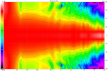
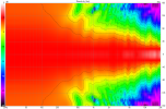
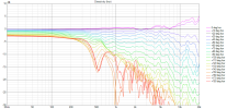
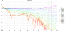
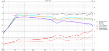
As the on axis and power Response looked pretty promising and Sound was good i have gone full cracy with the passive Crossover to flatten out the responses just to show it can be done. It helps that the Cardioid Design throws up less peaks and dips in room even without windowing the response (at least much more then with conventional Speakers). Still this is like the 100th version of Crossover that is printed here and the parts are ~200$/€ per Speaker - not usind anything special or more expensive then needed or reasonable (no fancy coils or capacitors).
In the picture is a preliminary Crossover as the final one still needs some parts to arrive. The preliminary one has a more wavy frequency response and is corrected with eq (Wiim Pro) to mimic the response given with the final crossover. It is in my crossover test boxes and not tidy at all. The final crossover will look better but still be huge and not fit into the speaker.
How does it sound? Very neutral and uncolored, light and transparent, lively and fresh without being tiring. My wife and daughter wo dont know much about speakers but love Music preferred this speaker against Neumann KH150, Genelec 8341 and a big active 3-Way i made myself as well as another good sounding 2-Way Speaker (Heissmann Acoustics DXT-Mon 182. To be fair i used all Speakers "as is" and without room correction - on the actives i tried the dip switches to maybe improve sound. If set up perfectly and EQd to the room other speakers may still sound better. Not doing this the Cardomon SB has the edge.
However not all is great:
The sensitivity is low (~80db/2,84V but i have to check closer with final crossover).
The absolute Bass output that can be achived is low (and the limiting factor if the speaker is not used with a sub). Harmonic Distortion of the SB17 is superbly low in the Midrange but not so much in the bass - in addition you would get a lot of IMD if you push it hard.
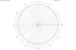
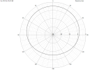
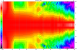
Horizontal dispersion is great but vertical is not. This can not be seen in power Response as there is lobing that fills the gap. Not sure why though as i would expect a bigger Dip in power Response then can be seen in the graph.
Tweeter/Waveguide Response is not as smooth as could be (SB Acoustics Beryllium Waveguide Tweeter, Purify Tweeter, ASCILAB are all better).
Cost - With 4 Drivers per side and a huge Crossover and the realistic need for a sub the speaker is no bargain. Its worth for the sound quality though.
The Design is inconsequential - If a Subwoofer and DSP has to be used anyway for best Sound anyway one could save a lot on Crossover parts and not correct Peaks and Dips in the Crossover but in DSP instead.
I may have fallen into a trap and corrected a measurement error in my crossover (with my setup for measurement all Speakers have a 200Khz peak and 300Khz Dip). Luckily one Resistor fixes that and can easily be changed. As i however tend to listen in spaces where this exact peak and dip applies i propably let the fix in place - just be aware that this may be room correction and not Speaker correction.
For all of these Reasons mentioned i consider this more of a proof of concept and beyond a reasonable DIY Project for anyone else.
I also have to mention that a Dutch &Dutch or Kii 3/7 may just plainly be a better Speaker - propably the same is true for less expensive Cardioid ones like the Mesanovic CDM65 or Buchardt A500.

