i am really impressed!
Do you have some pictures from the inside?
(did you ground the cinch outputs of the RME Dac to the housing of the tapedeck?, how are the vu meters connected?,...)
greetz Jim
Thank you for your kind words
@Jim Tonic .
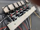
On the outside it looks ok when caught at the right angle and when viewed with a squint, much less so on the inside where I ran out of commitment and talent. My credibility in tatters, I am releasing a picture of the mess on the inside, it's not pretty. <hangs head in shame>.
On reflection, and now knowing that I wouldn't end up using circuitry on the Sony main PCB, I should have stripped the cassette deck and started from a bare chassis.
On a positive note, it amazes me that something I have put together is allowed in our living room, even more so that it is still being used by my family!
I use the BNC SPDIF output from the Allo Digione hat to drive my external RME DAC, I believe the RPi + Hat are grounded via its SMPSU.
Top center of the image is my effort at tapping into the USB QWERTY keyboard encoder PCB to map the cassette mech 'piano keys' into the RPI to give manual operation of key functions, Rew, Stop, Play, FF, 'Next track' (formally Rec) and Pause. The shrink wrapped bundle under the 'P' clip is the matrix formed by the cables coming from the microswitches operated by the cassette 'piano keys' emulating a keyboard. Centre of the image are the 5V DC-DC converter which draws its supply from a 16V regulated rail from the original PSU and the internal DAC, required to generate an analogue line level signal for the VU meters with the New VU meter driver board lower right. I did originally tap into the original cassette deck VU driver circuit on the Sony main PCB, but I found it didn't respond very well and some months later I bought a dedicated VU meter driver which now runs off the 5V DC to DC converter.
The original Sony main board has now been removed and a load of redundant wiring has gone with it, although some still remains (I dare not cut anymore out in case something stops working), this made space for the new VU meter driver PCB, (black PCB). I have kept the original supply transformer and regulators which now provide supplies to the VU meter circuits and the back lights. The whole VU meter system and PSUs can be switched off from the front switch leaving the RPI to work as it would normally from its own supply. My wiring to the newly replaced VU meter filament lamps, lower left, is a mess, I was worried that I might snap the fragile wires if I wrangled them into a loom. (Well, that's my excuse for not tidying it).
Microswitches fitted to the original cassette deck 'piano keys', quite a lot of effort given the presence of a 7" touch screen!
And the outside view, inner mess not visible.


")