DDF
Addicted to Fun and Learning
- Joined
- Dec 31, 2018
- Messages
- 617
- Likes
- 1,362
The wide baffle design of the Ellipsa or Stradivari is very interesting and I would recommend looking at Troels Gravesen's writings on that approach.
I was interested in some of Grimm's claims so investigated how a wide baffle moves the diffraction peak and affects the in room response. Details attached and here: https://www.diyaudio.com/forums/mul...ros-cons-wide-baffles-study-grimm-ls-1-a.html
Grimm's philosophy: "What we can do is decide where to put the baffle-step frequency...If we can get reasonable, constant directivity above [300 Hz], we have a design spec!”
Some high level observations:
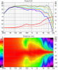
- The differences in power response probably most distinguish the sound of a wide baffle relative to an equally well designed narrow baffle monitor: It puts the power response “hole” in a different frequency range (see below)
- The wider baffle decreases the off axis response from 200 to 700 Hz by ~ 3 dB, relative to the standard narrow baffle. A speaker with excess 600 Hz can sound “hollow”, so this tuning will be the opposite of that (less hollow than pure accuracy?), but can also reduce the clarity of bass lines or thin out guitars.
- Equalized to flat on axis, a narrow monitor will have up to 3dB less power response from 700 Hz to 1.2 kHz than a wide baffle speaker. A speaker with less energy in this range can sound less “punchy”
- The 500 Hz to 1 KHz region produces 35% of the intelligibility, while the range from 1 to 8KHz produces just 5% of the power but 60% of the intelligibility. So the wider speaker may offer enhanced intelligibility
")