• WANTED: Happy members who like to discuss audio and other topics related to our interest. Desire to learn and share knowledge of science required. There are many reviews of audio hardware and expert members to help answer your questions. Click here to have your audio equipment measured for free!

Colin James Wonfor

Active Member
Technical Expert
The Wonf
Joined
Oct 24, 2016
Messages
210
Likes
182
Location
London< UK
The Brief History of my life with SECA designs

The SECA amplifier designs have been in use for a long time from the early days of valves to the present day. With valves it was a simple matter of biasing the triode and having a transformer coupling to the loudspeaker. Even the first transistor design had transformer coupling, this was OK for audio but the low frequency was poor and the top frequency response was very poor.
Much later people like Glen Croft did make some very lovely direct coupled valve amps but most I recall were push-pull.
Push-pull A Class designs have also been around for a long time but there is always a tiny bit of crossover distortion and the sound character is nice but for me not fulfilling.
The John Linsey Hood designs are very good but still for me lack that deep solid deep bass.
Noel Keywood also made a lovely sounding SECA design but like all semi-conductor design they do get hot.
Mullard toyed with the design in the 1960 – 1970 but to produce the constant current in the output stage they use a huge choke.
My first design of the amp section was not designed to play music; it was a piece of test equipment I made to test CUK converters (PSU) on dynamic loads. It soon dawned on me as my hobby then was making my own Hi-fi this concept would make an ideal SECA design if only I could control the current.
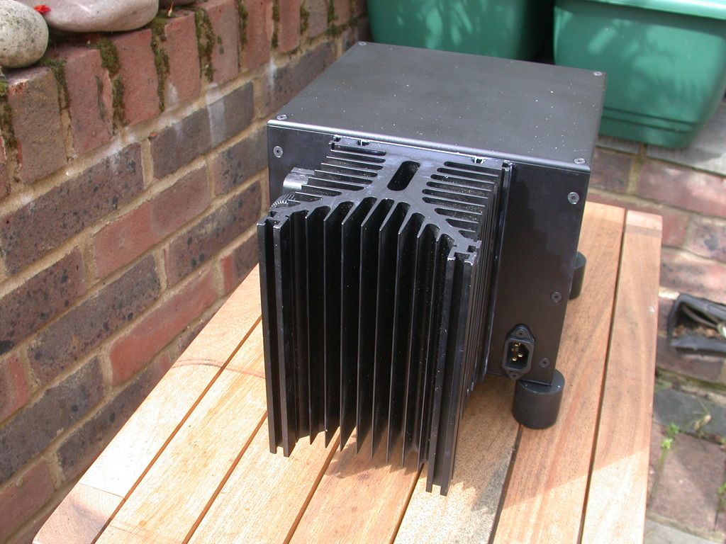
Now I made my first one in 1972 it was just 12W into 8R it used a FET as the amp and a Darlington as the constant current source. It was in a box supplied by RS this box was also used in the early Albarry Amps. This original amp I made is still working it under the floor boards of my friend Dave Harris’s home in Southend running a old pair of IMF speaker which I think Alan Elsdon sold him (Sondale).
After this FET’s were not as they are now the one I used were only about 15A and 60W and the SOA (Safe Operating Area) was crap to say the least compared to now.
Alan Elsdon and I decided to push this to the limit he was on chatting terms with Martin Collums at the time so the first 50W amp was made it used a large number of IRF140 and lots of 2N3055 each paired up with its own BD139 to form a darling stage. Did it get hot oh yes it did but Martin did hear it and I recall he liked it. Alan I then decide bigger was better still only 50W we had made very large Blue boxes and massive heatsinks , these welding box look a likes were test at Etude in Belgium and it was so relaxing the 10 or so people auditioning them all fell asleep. Marc Van-Meobeke and his wife Rita loved them, but to be honest it was a bastard to make and to keep cool.
The I started MIH which became Magnum and A Class Designs for a while was forgotten, Alan and I went on to do Dreadnoughts and then I set up Inca Tech (the Claymore birth place).
Now of, I go around the world designing large and small PSU for a few years to earn a living.
TOCA these huge amps were originally design for two reasons only. 1) To be the largest in the world and, 2) to provide the backer an inlet into the UK with leather product. But out of it came the Oberon and lots of 20W TOCA and a 50W,100W,200W,300W mono range of SECA’s some of which you may have listened to.
OK of I go again around the world working for some fun start up companies and others.
Back in the UK (Scotland) I got offered a job designing underwater equipment for seismic listening (almost audio 10mHz – 100mHz) proper bass. In Somerset so that how I got to live in that lovely county, seismic movements.
Now I started Catch XXII which became thieving morons based on my designs of cable and my desire to make a very good SECA the Iridium. Now we have much better components that do not vaporise when turned ON.
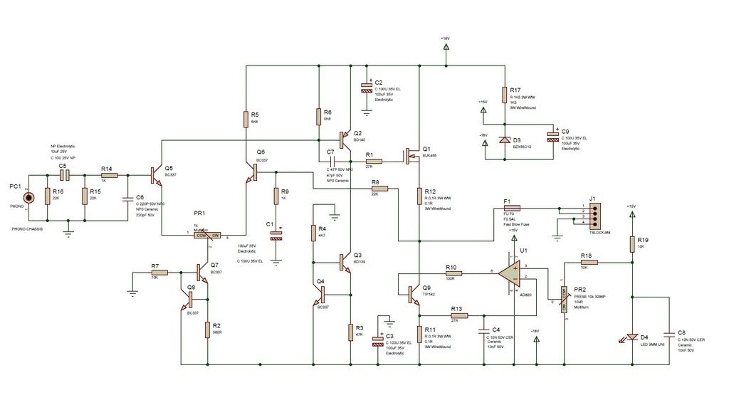
The Design of the KISS SECA Pt 1 Version 1
The un-complex looking design is based on the original design under those floor boards in Southend but now with substantially better components (oh yes). In the design published in Wireless World we had current drivers to push the 5 – 80 FET,s to their peak performance but we are now using FET.s with a much lower gate capacitance and thus it is no longer require there was few remarks of hatred by somebody who wondered why I did not use a DC servo but all servo’s in amps cause distortion at lower frequency and I have seen a few of his un-used designs in other companies that to be honest where misguided and failed to meet the mark.
 
OP
Colin James Wonfor

Colin James Wonfor

Active Member
Technical Expert
The Wonf
Joined
Oct 24, 2016
Messages
210
Likes
182
Location
London< UK
Amp%20A%20Class%20Kit%20SECA%20_zpsxitiugcj.jpg

From left to right you can see the input socket PC1, it is terminated with a 22K R16 resistor followed by a DC blocking capacitor C5 and another 22K R15. This make the input to the amplifier aproximatly 10K ohm, why did I choose that well most pre-amp will drive it, ringing in poor cables is reduced but the main reason is if you unplug it is less likely to blow you speaker up with a loud BUZZ. C5 will determine to low frequency roll of point. And with a simple calculator we can see that the -3dB roll of point is about 1Hz. R14 1K and C6 220pF is a used to limit high frequency RFI and Taxi etc.
Q5 and Q6 are low noise NPN transistor, it would be nice to have a match pair here but it would cost more, you could buy a digital meter with HFE on it and a few hundred transistors and match them yourself (I did) but time and boredom is killer. And to do it properly a nice Tektronixs curve tracer would be nice, Naim have one nice kit and a small mortgage to buy it. This Long Tail Pair Q5 and Q6, are supplied with a constant current generated by Q7 and Q8 both NPN transistors and the same type as Q5 and Q6 BC849B you can use other as long as they are the same type and with luck were you get matched pairs for Q5,Q6. The current is determined by the value of R14 and the Base Emitter Vf i.e. 0.6V , I = 0.6V/560R for the Basic and 0.6V/330R for the all FET output version and please note the same PCB is used for both.
The Long Tailed Pair drive the PNP Transistor BD140 Q2 this transistor also is running class A with it current supplied by another constant current source comprising or two transistors of Q3 and Q4. The bias current of the BD140 is set again by 0.6V/R3 in the basic design this 0.6V/47R giving us 12mA and on the super version 0.6V/27R i.e. 22mA, the higher current is needed to overcome the charge capacitance in the much larger current wise MOS FET Q1 and in the basic design this is IRFP4410ZPBF and in the other a IRFP4368PF. Also note the anti-parasitic capacitor connected to the Base and Collector of Q2 has changed from 47pF to 22pF due to the loading of the FET Q1.
Q1 is heavily biased into Class A and is a true SECA output stage, the current source for this is provided by Q9 a TIP142 Darlington or the FET another IRFP4368PF. The control of the current in Q9 is provide for by the Rail to Rail Operational Amplifier Intergraded Circuit (R-R Op-Amp). It sense the voltage across R11 a 3W Wire Wound 0.1R resistor. The reference control voltage to the R-R Op Amp is generated by voltage across the Green LED, I use Green LEED this for this because they are cheap and produce very little noise compared with a Red LED and cheaper than a precession reference diode. The R-R Op-Amp get it power from the main +V via a resistor R17 1K5 3W and this is shunt regulated with a zener diode D3 connected via its Anode to the –V rail.
To fine tune the reference voltage we us a resistor R19 to the LED a 10K and R18 a 10K thisis connected to the current set trimming preset to adjust the current. On the Basic version with the Darlington transistor Q9 the base is driven via R10 a 100R resistor on the next version R10 is replace from a 100R to 470R this tames the FET and allow it to turn on slower. The current feedback sense resistor R13 on Version one is 27R and on version two it is still 27R.
Now using old Ohms law 1A across 100mR is 100mV so to set up our current we adjust PR2 so we can read across R11 a 100mV for every amp, i.e. as my heatsink is huge I set mine to 270mV or 2.7Amps. Next with the DVM on the speaker terminal we adjust PR2 to read close to zero volts thus the DC offset. Ideally no load is connected and 100mV either positive or negative is ok Mine is reading +27uV on the left and -75uV on the right with the plus (red) terminal of the DVM connected to the speaker out and the negative (black) to the OV outputs,

HEAT and Dissipation

The beast I made firstly in this series was very basic no regulated PSU and with Darlington’s i.e. Version one. My power supply was set at ±18VDC on load unregulated with a small 225VA toridal transformer with two outputs winding at 0-15VAC each.
So now with no signal I have 2.7A at 18V on the FET Q1 and on the Darlington Q9, so our total dissipation is about 98W, with a estimated (at this point) 22W of output power into 6R, not allowing for the voltage drop across the constant current source or the minimum voltage across the FET given a Vgs of about 4V, so we could loss 6V swing in out output.
Now that 98W lets say 100W has to dissipated to something OK it could be the hot water tank but not practical, we could use a FAN assist heatsink but the wind noise would hide the music from the sounds of Meatloaf. So it looks like standard convection type heatsink, now we are talking big.

Part 2 Heavy Metal

Now with just a KISS thought we could calculate the heatsink required but I hate maths, and most thing can be done much simpler with the Sherlock approach .
i.e. with a 30ºC ambient for example and a 0.3Cº/W heatsink at 100W we get a 30ºC rise above ambient so 60ºC a bit hot to handle especial with children and cats about.
So with a 0.2Cº/W we get 20ºC rise above our 30ºC ambient (a hot UK summer!) and a 50ºC heatsink, maybe to be safe we should either exclude the cat and kids or use a grill covering to protect them. (I would move instead)
In this photo you can see how Sam and Paul mounted there differently Pauls is much better as the Copper can a) spread the heat faster and b) have less thermal barriers to break.
Also not on Paul the Heatsink fins are spread over a larger area and not height as with Sam’s ,the will both work fine, and it depends on you funds which method you choose.
Mine in the last photo uses the case clamped to the heatsink (case supplied with thanks from Paul) and then spread the heat into the same heatsinks as Sam’s baby.
 
OP
Colin James Wonfor

Colin James Wonfor

Active Member
Technical Expert
The Wonf
Joined
Oct 24, 2016
Messages
210
Likes
182
Location
London< UK
TEST%20BEFORE%20CLEAN_zpst9exkkj5.jpg


lso I have rearranged the PSU which has with this simple mod will force the PSU board to close down in constant current mode. Less chance of smouldering FET,s

Change R10 to 1K and R11 to 10K, Change R13 to 1K and R10 to 10K as in this circuit.

main%20reg_zpsekfgsj3n.jpg

I have designed the kit to be very easy to build, and have a minimum of components. SECA amps have inherently simple circuits, yet Colin has reduced the component count further from his earlier designs.

You'll need:

One power amp pcb/channel.

fetch.php


Preparing components

Bend the resistor wire ends - this is the 1K5 3W.

fetch.php


More to follow
 
OP
Colin James Wonfor

Colin James Wonfor

Active Member
Technical Expert
The Wonf
Joined
Oct 24, 2016
Messages
210
Likes
182
Location
London< UK
The 100mR or 0.1R 3W.

fetch.php


The smaller resistors.

fetch.php


The resistors mounted.

fetch.php


Capacitor C5 mounted.

fetch.php


The current control pre-set near the AD820 op-amp.

fetch.php


Fuse holder and 18-0V, 0-18V power input for the transformer.

fetch.php


Bending and mounting the 6Amp diodes in the bridge rectifier.

fetch.php


fetch.php


Mounting the Green LED that is used to generate the reference voltage for the current control. Note: the long leg that is near the hole it will be soldered into is the Anode.

fetch.php


LED with the two 10nF caps behind. NOTE C4 is now not fitted.


One of the two 33,000uF bulk capacitors. Note: the stripe in the case is the negative terminal. Always check these or big bang will be louder than the music! Just a quick note here some place do not stock the 33,000uF any more and you can fit 22,000uF or has some DIYer have fitted 47,000uF me included, but they must all be 25V or above.

fetch.php


Mounting the Op-Amp, AD820.

fetch.php


More to follow.
 
OP
Colin James Wonfor

Colin James Wonfor

Active Member
Technical Expert
The Wonf
Joined
Oct 24, 2016
Messages
210
Likes
182
Location
London< UK
Case or cases
You can build the SECA kit into a single box, or as two monoblocks. This page shows some of the cases we've used.

From ModuShop in Italy www.modushop.biz/site/index.php?route=product/product&path=66_97_107&product_id=218

From Amazon or a PC supplier

I built a SECA has been built as a pair of monoblocks using two www.amazon.co.uk/Sharkoon-CA-M-Micro-ATX-Case/dp/B00MLU5ZNO?ie=UTF8&colid=2KV320CSFKZGY&coliid=I2ENTN1OHK8M7S&redirect=true&redirect=true&ref_=s9_wish_gw_d99_g147_i4
When these cases were bought, they were £36 each, but at the time of writing, they were considerably more, so please check the pricing before ordering.

The drive transistors BD139 and the BD140, see there orientation and the BD140 is on the right. Solder them closed as the PCB acts as a small heatsink. Also mount the BC337 close but not tight to the PCB.

11924367_1478654805786212_6409623771591340121_o.jpg


Here are the pair of PCB's completed.

11894552_1478655252452834_8173960998400096901_o.jpg


On set up insure the IQ preset is Anticlockwise and the DC offset is centre.

PCB 1 , 5Hz - 100KHz Flat PCB 2, 5Hz - 100KHz Flat at full power (15W) in this case.
DC offset -3.2mV 0.3mV
I/P Z 13.5K 13.5K
Damping 1150 1128 with a 250VA transformer tag on.
Phase angle 20Hz - 20KHz -,+ 1 deg both PCB,s

Also not the insulators under the MOS FETs a small amount of heatsink compound.

A small error was found on the PCB so the Zener is placed and soldered.

The Zener fit under the PCB on the IC Pin 7 is the Kathode the marked end the Anode fit on PIN 4, Pin 1 is marked on the chip/IC with a dot or a circle. Anti clockwise it goes 1,2,3,4, opposite 4 is pin5 then 6,7,8
As viewed from the top legs down.

ad820.ashx
8176-large.jpg


Here is a completed one channel with the additional add PSU circuit board.

P9110207_zpsftqrrxwe.jpg


Another DIY

DSCN2691.jpg


P9160224_zpskjgkgmr3.jpg


All four PCB required for the super charged version.

Chris%20PCBs_zpsiwzuqlld.jpg


More to follow.
 

amirm

Founder/Admin
Staff Member
CFO (Chief Fun Officer)
Joined
Feb 13, 2016
Messages
44,658
Likes
240,923
Location
Seattle Area
OP
Colin James Wonfor

Colin James Wonfor

Active Member
Technical Expert
The Wonf
Joined
Oct 24, 2016
Messages
210
Likes
182
Location
London< UK
Amirm, I am confused I have a msg that say this is not the site for my lack of skills, and I should go to a DIY site.
Mmm well I have 3 degrees a bit rusty and I have design loads of stuff.
So please forgive me if I have read these msg wrong but I seem not to be needed here.
Now to put thing a bit more clearly I am also very dyslexic, and I have had stroke which has left me only with my left side work well and I have had now two ticker ops, with mech bits added and ticker being the right word.
So have I read it wrong or right??
 

Thomas savage

Grand Contributor
The Watchman
Forum Donor
Joined
Feb 24, 2016
Messages
10,260
Likes
16,305
Location
uk, taunton
Amirm, I am confused I have a msg that say this is not the site for my lack of skills, and I should go to a DIY site.
Mmm well I have 3 degrees a bit rusty and I have design loads of stuff.
So please forgive me if I have read these msg wrong but I seem not to be needed here.
Now to put thing a bit more clearly I am also very dyslexic, and I have had stroke which has left me only with my left side work well and I have had now two ticker ops, with mech bits added and ticker being the right word.
So have I read it wrong or right??
I'm really pleased to see a man with the obvious deep knowledge and understanding we need here at ASR posting such engaging material..

I'm also dyslexic ..
 
OP
Colin James Wonfor

Colin James Wonfor

Active Member
Technical Expert
The Wonf
Joined
Oct 24, 2016
Messages
210
Likes
182
Location
London< UK
A bloody pain this dyslexic stuff, I have read things a least 3 times and plural and singular always get me.
 

Thomas savage

Grand Contributor
The Watchman
Forum Donor
Joined
Feb 24, 2016
Messages
10,260
Likes
16,305
Location
uk, taunton
A bloody pain this dyslexic stuff, I have read things a least 3 times and plural and singular always get me.
Yea it's irritating but also seems to have some upsides.. I tend not to seperate or partition myself off and take dyslexia on as a important/ integral part of what makes me... Me.
 
OP
Colin James Wonfor

Colin James Wonfor

Active Member
Technical Expert
The Wonf
Joined
Oct 24, 2016
Messages
210
Likes
182
Location
London< UK
Next part as I have started I will finish.

Configuration with and without PSU board.

PCB%20CONNECTIONS_zpss7e1rloc.jpg

With the soft start option.

12045384_1518540221797670_3875302107393835799_o.jpg


The Sliding or Dynamic PSU

As you can see the +V and –V regulator are based on the LM317 and LM337 chips, these are drive current gain stages and have a very simply current fold back current limit using 0.1R resistors to set this to about 6A.

This current limit allow the 10,000uF and the SECA’ s 33,000uF capacitors to charge much slower and this will increase their life and reduce the ON thump.

The basic just SECA board has a ripple voltage of about 500mV but with the PSU this is reduced to approx 5mV, this will show itself as more detail at low levels when using the PSU together with the SECA.

The loses across the FET are there because we have a Gate Source voltage of about 4 – 5V so the FET cannot drive to the +V rail, the Darlington in the original has a voltage across it of about 2V and thus it cannot swing to the –V. So to use the full range of the power/volts available we use the PSU board with all the advantages mention before. In version 2 with the 2 FET’s the –V is not such a problem as we only lose about 200mV max.

Now as the output approaches the max regulated +V or –V on peaks the PSU ref is also moved and as it approaches 10V peak the PSU output voltage changes and allow the FET/Darlington to get to the max voltage it can, this gives you more punch and dynamic, this will show up on deeper bass and fresh top end.

Heatsink guide.


fetch


Basic circuit but DO REMOVE C4

fetch


BOM replace Q9 with FET part.

fetch


It a 24VDC fan running on a 7VAC rectified with only a 47uF capacitance for smoothing and this kick starts the fan, but not enough energy to run it fast, much more elegant then a big resistor to drop the volts.

Fan%20PSU_zpsfbi4kpbh.jpg


Heatsink Compound

Some of us would use a thick dollop of heatsink compound spread like soft cheese NO NO do not a thin smear is all you must use and ensure you use M3 screw when mounting transistor and FET’s.

Also a safety tip DO NOT GET THIS IN YOU EYES it is not nice, I’ve tried it worse the arc eye.

Just a mod to add 7W more.

This tiny mod could add up to another 7W to the SECA without a heat increase.

13403228_10209800316468858_3302362572801648789_o.jpg


seca%201.jpg


seca%202.png
 

amirm

Founder/Admin
Staff Member
CFO (Chief Fun Officer)
Joined
Feb 13, 2016
Messages
44,658
Likes
240,923
Location
Seattle Area
Amirm, I am confused I have a msg that say this is not the site for my lack of skills, and I should go to a DIY site.
Mmm well I have 3 degrees a bit rusty and I have design loads of stuff.
So please forgive me if I have read these msg wrong but I seem not to be needed here.
Who is saying that??? Your skills and background are superb. I am reading, enjoying, and learning from your posts already.

Our forum is small right now but growing so you may not get as much feedback as you would in a DIY forum. But no one should be telling you whatsoever that you should not post here.

Your dyslexia is also not a problem at all. You are communicating just fine. Wish I could after what you have gone through! :)
 

amirm

Founder/Admin
Staff Member
CFO (Chief Fun Officer)
Joined
Feb 13, 2016
Messages
44,658
Likes
240,923
Location
Seattle Area
OP
Colin James Wonfor

Colin James Wonfor

Active Member
Technical Expert
The Wonf
Joined
Oct 24, 2016
Messages
210
Likes
182
Location
London< UK
I like Nelson and his work he has open the eye's of many people in the sense that we do not 400W amps to have good music with a great sound stage and clarity, a good man.
In the 1990,s he did is first 50W A Class and as a challenge I did a 300W SECA design called a TOCA, befroe that I was contented with 12W, he he

The caption is wrong but here is one channel, good god I was young then.

12800405_1563782217273470_1483985633035746140_n.jpg
 
OP
Colin James Wonfor

Colin James Wonfor

Active Member
Technical Expert
The Wonf
Joined
Oct 24, 2016
Messages
210
Likes
182
Location
London< UK
A baby one I did some 100KW stuff for the MOD a long time ago, with 1200V 300A IGBT wicked beast.
 
OP
Colin James Wonfor

Colin James Wonfor

Active Member
Technical Expert
The Wonf
Joined
Oct 24, 2016
Messages
210
Likes
182
Location
London< UK
Dan sat nest to me at the show in London and he thought I was crazy, but he was a nice guy, Ramda Heathrow 1995 ish
 
Top Bottom