• WANTED: Happy members who like to discuss audio and other topics related to our interest. Desire to learn and share knowledge of science required. There are many reviews of audio hardware and expert members to help answer your questions. Click here to have your audio equipment measured for free!

Multichannel audio on a Pi will get a whole lot easier and cheaper!

Frunse

Active Member
Joined
Feb 21, 2024
Messages
133
Likes
20
Great work! :D
Do you still have plans for hardware ASRCs to allow different word-sizes and sample-rates on the I²S input and output of the RPi5?
Yes got the ASRC Boards and waiting for my new ERSA NANO MK2 Soldering Iron for this little nasty SMD Parts ;)
Then i will build it up and will test it.

So i can compare both Options, ASRC or Arduino with Samplerate Detection.

Robert
 

Frunse

Active Member
Joined
Feb 21, 2024
Messages
133
Likes
20
Glad to see good progress. I have a question, that we probably discussed like 3 times before but I don't remember now. Why don't you do the LRclk sample rate measurement directly in the RPi? Would save you a few parts and all the i2c communication with the Arduino.
Yes, for now i find it more complicated to do it on Pi, my Progress on Arduino get it faster but after that i want to have the possibility to make it on RPI to, that why i use the i2C Connection in between for flexibility.
I can try it to learn how it will go on RPI but for now its easier for me with Arduino Programming than on RPI.
I did my Reserch yesterday on both and read a lot and found solution for RPI and Arduino on I2C Communication.

I am on the beginning for this Journey so let see how far it wil go.

Its only an decision on Software side.
So not an Big deal to remove the Arduino later.

One Big step is to get the RS485 Communication to the Amps running (Volumecontrol) for now it seems easier on Arduino for me also.
But i use an ttl to RS485 Boart and may be i could get it running alo on an PCF8475A Chip so i can use it on I2C aso, didn't need realy fast transfere rates.

Only 4x 8Bit for 2 XLR Channels to transfere.

That i need to check first to see how it will go never done it before ;) It's all new for me.

I will check also the Relais or PGA 4311 (4 Channels / 2 XLR Possible) option, didn't have to much room in my AMP Enclousure and PGA Chip will become more cheeper than the Relais option and more Compact.

So lots to Prototype Step after Step ;)

I have already an 2x PGA2310 Prototype Board i build years ago for Microchip Processor Programming and it was working well so i can test it now too.

Robert
 

Attachments

  • 4 Channel PGA2310.jpg
    4 Channel PGA2310.jpg
    183.1 KB · Views: 30
Last edited:
  • Like
Reactions: MCH

Frunse

Active Member
Joined
Feb 21, 2024
Messages
133
Likes
20
Hello did an little Rework of my I2S Board Schematic, may be anyone could do an short look, if this could work, may be i didn't see any Problems on this design.

This way you could use 1 to 8 Multichannel I2S Input's (start with 4 and later you could easely add some if you want)

All Signal wire's, exactly have the same Length on Multichannel I2S Input (Do-D3, LCRK, BCLK) only from different I2S Input Boards they hace different lngth to Raspberry.

Robert
 

Attachments

  • I2S Switch Motherboard.pdf
    321.5 KB · Views: 22
  • 74HC573 Board.pdf
    47.3 KB · Views: 16
  • 3D Modell.pdf
    614.4 KB · Views: 23
  • I2S_Motherboard.jpg
    I2S_Motherboard.jpg
    149.2 KB · Views: 12
  • 74HC573 Board.jpg
    74HC573 Board.jpg
    121.9 KB · Views: 13
Last edited:

renne

Member
Joined
Feb 29, 2024
Messages
26
Likes
1
Yes got the ASRC Boards and waiting for my new ERSA NANO MK2 Soldering Iron for this little nasty SMD Parts ;)
If you want to (de-)solder existing SMD-PCBs I suggest to have a look at reflow workstations.
If designing new PCBs self-soldering PCBs would simplify soldering SMD parts.
 

renne

Member
Joined
Feb 29, 2024
Messages
26
Likes
1
Hello did an little Rework of my I2S Board Schematic, may be anyone could do an short look, if this could work, may be i didn't see any Problems on this design.

This way you could use 1 to 8 Multichannel I2S Input's (start with 4 and later you could easely add some if you want)

All Signal wire's, exactly have the same Length on Multichannel I2S Input (Do-D3, LCRK, BCLK) only from different I2S Input Boards they hace different lngth to Raspberry.

Robert
Great idea!
Please check how the additional connectors influence the clock and data signals.
 

Frunse

Active Member
Joined
Feb 21, 2024
Messages
133
Likes
20
Great idea!
Please check how the additional connectors influence the clock and data signals.
I Changed already the design to U.FL Connectors ;)

Resolderstation is abit to expensive so i am fine with Ersa Nano and changed the Boards already.
Got also the right TIP Set for the most Soldering jobs :).
The New Soldering Tip change system is Buitiful, i love it, Changing Tip's in seconds without tools or waiting for cooldown.

Now i will use an 5PB1104PGGI (IC CLK BUFFER 1:4) for Clock distrebution to all 4 CS4821 so they have all the same wire length to the Clock !

Will Design an new Board too for Multichannel ASRC with 2x Raspberry Connector to Fit it between my I2S Motherboard and the Raspberry as an Option ;)

For the Boards only need to change some Wire with on KICAD then it will be rady to build i guess.

Reworked the ASRC Board's with an U.FL Connecter instead of an Crystal for the first Prototype!

One question to the Experts:

If i use this 5PB1104PGGI 1:4 Clock Buffer than i need to use an Powered Oscilattor (24,576MHz) instead of that Crystal with very good PPM Value right?

Could i use the same Clockbuffer's to split the incomming LCRK and BCLK Lines to that 4 ASRC Boards too???


Robert
 

Attachments

  • Test 1 Bottom.jpg
    Test 1 Bottom.jpg
    114.6 KB · Views: 23
  • I2S_Motherboard.jpg
    I2S_Motherboard.jpg
    113.6 KB · Views: 18
  • 74HC573 Board TOP.jpg
    74HC573 Board TOP.jpg
    104.7 KB · Views: 18
  • 74HC573 Board BOTTOM.jpg
    74HC573 Board BOTTOM.jpg
    97.4 KB · Views: 17
  • ERSA TIP.jpg
    ERSA TIP.jpg
    125.9 KB · Views: 21
  • ASRC_Board.jpg
    ASRC_Board.jpg
    709.8 KB · Views: 13
Last edited:

Frunse

Active Member
Joined
Feb 21, 2024
Messages
133
Likes
20
I got an new idea for 16 Channel Analogue Volumecontrol with an cheep CD4051 8:1 Multiplexer on Virtual Ground of an Opamp negativ Input.

Found an Example on an old ELEKTOR Boock and adpted it for XLR Connection (Symetrical Signal).

Will build an Prototype for first Test One or two Channels.

But i need to use 6 PCF8575 16Bit I2C Expander for 16 Analogue Channel. (16x6Bit=96 I/O's, so 6 16Bit Chip's needed)
They need 6Bit for 64 Steps (1.25dB Steps)

Alterntiv will be to use 8 Muse 72320 Chip instead of 8 PGA2310.
PGA2311 and 4311 didn't have the required Voltageswing for 4VRMS.
And they didnt have an OPAMP inchip so the Soundquality would depend on the used OPAMPS and they could be replaced individualy. But this will cost alot :(

Robert
 

Attachments

  • Elektro Multiplex Volume.pdf
    445.2 KB · Views: 16

phofman

Addicted to Fun and Learning
Joined
Apr 13, 2021
Messages
506
Likes
331
@Frunse: Do you have any data to support those circuits would be better than the digital VC in your DAC chips?

CD4051 analog switch has THD of 0.15% - 0.3% - check the datasheet. No noise figure, but I kind of do not think your circuit with so many resistors and opamps in the signal path will be ultra low-noise.

PGA2310 is much better, but IMO still comparable to a good DAC chip volume control.

IMHO any integrated analog volume control has no benefit compared to a good DAC chip (of course unless some unwanted-peak safety is considered). A well-implemented signal relay attenuator is probably superior to the digital volume control. Maybe even that would not surpass well-implemented top ESS DAC chips.
 

Frunse

Active Member
Joined
Feb 21, 2024
Messages
133
Likes
20
@Frunse: Do you have any data to support those circuits would be better than the digital VC in your DAC chips?

CD4051 analog switch has THD of 0.15% - 0.3% - check the datasheet. No noise figure, but I kind of do not think your circuit with so many resistors and opamps in the signal path will be ultra low-noise.

PGA2310 is much better, but IMO still comparable to a good DAC chip volume control.

IMHO any integrated analog volume control has no benefit compared to a good DAC chip (of course unless some unwanted-peak safety is considered). A well-implemented signal relay attenuator is probably superior to the digital volume control. Maybe even that would not surpass well-implemented top ESS DAC chips.
Yes but the CD4051 is connected to Virtual Ground Point of that Opamp, so the THD of an CD4051 doesn't matter. there is always 0V at this Point, Thats the Magic on that Design ;)! You could also use Relays or an Dac Ladder there but i guess there are no Differnces because its 0V all the Time on that Devices.
But would like to compare / test it.
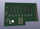
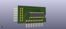
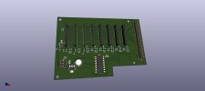
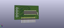
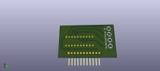
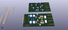
The Muse 72320 seems to be better than the PGA2310, but need more Parts specialy bigger Caps 4x 100uF/25V around the Chip. Thats Matter if yuo need 8 Chips of them on a PCB / Enclousure.
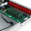
Did already a Board Design for Stereo but not ready yet, i split it to an XLR Inputboard and the Muse Chip with Outputboard. You could Connect than 8 of that Boards to one Motherboard. (Thats around 50-60Euro only in Parts for Stereo without the Board :( )

The Basic Design's (PGA, MUSE, and other) i found here:

https://hifiocean.com

I relay want to compare all possibilities.

PGA2310 i have already for testing.
Relaisboards also i have here but also there, i gues i need an Buffer OPAMP on the Outs for 5-10M XLR Wirelength Driving. Input is 4VRMS but on Out it will be halve or less.

So many Options and at the End without any of them it sounds the Best LOL ;) Probably

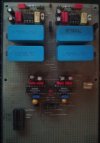
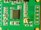
By the way, ELEKTOR did measure his CMOS Switchboard with that CD4051 (Volume) and CD4053 (Inputswitching) and got this Value with old NE5532 OPAMP's:

Noise >110dB @ 1V 20kHz
Channelseperation >110dB @ 1V 20kHz
THD <0,005% @ 1V 20kHz
THD <0,01% @ 3V 20kHz
Max possible Vout = 3,5V RMS RCA (7V RMS XLR)

So like i told above the bad Value's of the CD4051 didn't Matter i guess ;)

Robert
 

Attachments

  • MUSES72320 16Channel.jpg
    MUSES72320 16Channel.jpg
    155.2 KB · Views: 11
Last edited:

phofman

Addicted to Fun and Learning
Joined
Apr 13, 2021
Messages
506
Likes
331
Yes but the CD4051 is connected to Virtual Ground Point of that Opamp, so the THD of an CD4051 doesn't matter. there is always 0V at this Point, Thats the Magic on that Design ;)!
Hm, please correct me if I am wrong. The analog mux is part of a voltage divider between outputs of U3A and U7A where U7A tries to keep its inverting input at virtual GND (i.e. equal to its noninverting input). To get 0V at the inv. input, a current must flow through the voltage divider, i.e. through the analog mux. This current has the same waveform as the input voltage signal. If the resistance of the analog mux is dependent on the applied voltage (induced by the flowing current), it will change the divider ratio -> distort the signal.

But I may be wrong.
 

Frunse

Active Member
Joined
Feb 21, 2024
Messages
133
Likes
20
Hm, please correct me if I am wrong. The analog mux is part of a voltage divider between outputs of U3A and U7A where U7A tries to keep its inverting input at virtual GND (i.e. equal to its noninverting input). To get 0V at the inv. input, a current must flow through the voltage divider, i.e. through the analog mux. This current has the same waveform as the input voltage signal. If the resistance of the analog mux is dependent on the applied voltage (induced by the flowing current), it will change the divider ratio -> distort the signal.

But I may be wrong.
I am not the designer of that but i realy want to measure it with an good OPAMP to learn something new ;).
I also guess even the Current has 0A on the Virtual Ground Point and the Mux, i can't declare why, but normal Ground's has alway 0 V / 0A or you has an Error Voltag or Error crurrent right?

Realy interesting stuff :) why this works with for that time relatively good Values. The Book is from 1993.

An Ingennear of my old Job used Dac Ladders on that Virtual Ground Point for any Purpose not only Audio to change Values by Mcu's and he also told me that you cant heare switching noises there because of that 0V Point \o/.

Anyway i will design an XLR Mono Board and test it only for funn ;) Cost not much Money only Time and the Board i will CNC Engrave by my self, need to learn this to.

Robert
 
Last edited:

phofman

Addicted to Fun and Learning
Joined
Apr 13, 2021
Messages
506
Likes
331
normal Ground's has alway 0 V / 0A or you has an Error Voltag or Error crurrent right?
I am afraid I do not understand. If a wire (zero resistance) has 0V potential against some common ground, such information does not say anything about a current running through that wire. A neutral wire from a 240V 2kW heater has zero voltage (against ground, you can touch it :) ) all the time, yet it carries 17 amps peaks.

An Ingennear of my old Job used Dac Ladders on that Virtual Ground Point for any Purpose not only Audio to change Values by Mcu's and he also told me that you cant heare switching noises there because of that 0V Point \o/.
IMO probably what he meant was switching at zero - but that is at the zero point of the signal, when no current is running. Then switching the attenuation ratio causes no jump in the current/voltage - since no current is running :) Here you get current running through the voltage divider, even if that specific point is at 0V. But the other side of the analog mux is not at zero voltage, because it has non-zero resistance and a current is running through it.

Modern analog switches have much lower Ron so their nonlinearity has a comparably lower effect - see e.g. https://www.ti.com/switches-multiplexers/analog/products.html#sort=3143typ;asc&

I am not saying it's a bad circuit but I do not think it can have better performance than a digital volume with a good modern DAC (i.e. low output noise/THD+N). I may be wrong though...
 

Frunse

Active Member
Joined
Feb 21, 2024
Messages
133
Likes
20
I am afraid I do not understand. If a wire (zero resistance) has 0V potential against some common ground, such information does not say anything about a current running through that wire. A neutral wire from a 240V 2kW heater has zero voltage (against ground, you can touch it :) ) all the time, yet it carries 17 amps peaks.


IMO probably what he meant was switching at zero - but that is at the zero point of the signal, when no current is running. Then switching the attenuation ratio causes no jump in the current/voltage - since no current is running :) Here you get current running through the voltage divider, even if that specific point is at 0V. But the other side of the analog mux is not at zero voltage, because it has non-zero resistance and a current is running through it.

Modern analog switches have much lower Ron so their nonlinearity has a comparably lower effect - see e.g. https://www.ti.com/switches-multiplexers/analog/products.html#sort=3143typ;asc&

I am not saying it's a bad circuit but I do not think it can have better performance than a digital volume with a good modern DAC (i.e. low output noise/THD+N). I may be wrong though...
Thx for the Information, there are Muxes with nternal SPI or I2C too, so may be thats an good replacment, need to check the Datasheets. Depends on the switch count.

And yes the Best performance has the Part thats not need to add ;)

Robert
 

somebodyelse

Major Contributor
Joined
Dec 5, 2018
Messages
3,780
Likes
3,090
Hm, please correct me if I am wrong. The analog mux is part of a voltage divider between outputs of U3A and U7A where U7A tries to keep its inverting input at virtual GND (i.e. equal to its noninverting input). To get 0V at the inv. input, a current must flow through the voltage divider, i.e. through the analog mux. This current has the same waveform as the input voltage signal. If the resistance of the analog mux is dependent on the applied voltage (induced by the flowing current), it will change the divider ratio -> distort the signal.

But I may be wrong.
Linsley Hood presented a similar arrangement for input switching with jfets iin 'Audio Electronics' (pages 136-138, fig 3.14) suggesting that if the resistors around it (input, feedback) are high relative to the on resistance of the switch then the effect of the change in on resistance is low - the question is whether it's low enough, which I guess is where the measurements would come in - I haven't looked for measurements to go with this schematic. I think this works because the input resistance and the on resistance of the mux form a potential divider, so the mux sees only a fraction of the input voltage swing, reducing the variation in on resistance.
 

Frunse

Active Member
Joined
Feb 21, 2024
Messages
133
Likes
20
Linsley Hood presented a similar arrangement for input switching with jfets iin 'Audio Electronics' (pages 136-138, fig 3.14) suggesting that if the resistors around it (input, feedback) are high relative to the on resistance of the switch then the effect of the change in on resistance is low - the question is whether it's low enough, which I guess is where the measurements would come in - I haven't looked for measurements to go with this schematic. I think this works because the input resistance and the on resistance of the mux form a potential divider, so the mux sees only a fraction of the input voltage swing, reducing the variation in on resistance.
Worth to look into it and build an Prototype i guess even only for testing, Leraning.

I saw this Multichannel Processor:
TONEWINNER AT-300 EXT 5.1 AV Processor
And it has this interesting Volumecontrol Borads with lots of Resistors not sure if this the same kind of VolumeControl it has also 16 Channels.
So it seems this are Stereo Boards. but not sure need to read on the Company Webpage about this

"
Precise volume control
Quite rare on this type of device, the volume control is here with resistance switching. Such integration allows a precise and non-destructive adjustment of the sound level.
"
But no Relays there so Multiplexer i guess.

Robert
 

Attachments

  • tonewinner-at-300-av-processor-home-theater-preamplifier-dolby-atmos-16-channels-934-736.jpg
    tonewinner-at-300-av-processor-home-theater-preamplifier-dolby-atmos-16-channels-934-736.jpg
    153.6 KB · Views: 22

phofman

Addicted to Fun and Learning
Joined
Apr 13, 2021
Messages
506
Likes
331
I think this works because the input resistance and the on resistance of the mux form a potential divider, so the mux sees only a fraction of the input voltage swing, reducing the variation in on resistance.
I agree, IMO the same effect is here - 120R of the mux vs. the 10k of the other resistor, times the mux THD => 0.2% THD * 0.01 ratio => some 0.002%, rough calculation. Absolutely inaudible. Yet IMO worse than performance of a good DAC chip.

IIRC Ivan talked about using FETs as input attenuator switches in his initial versions of his Cosmos Scaler attenuator, unmeasurable distortion. In the end he used relays anyway https://www.audiosciencereview.com/forum/index.php?attachments/dsc_1027-1-jpg.304240/ :)

Back to that attenuator - probably it's not about distortion, but about whether this type of analog attenuator can further attenuate noise floor from a good DAC. If not, IMO no technical reason to avoid digital VC and complicate the design with these analog circuits.
 

Frunse

Active Member
Joined
Feb 21, 2024
Messages
133
Likes
20
Or discreet transistors which may perform better than a mux. I suspect it's about having a good marketing story rather than performance though.
Dont forget the Money you need to integrate 8 PGA2310 or MUSE into this Processor. Some Resistors and diskrete Transistors with 2 Dual Opamps are much Cheeper i guess.
Robert
 

Frunse

Active Member
Joined
Feb 21, 2024
Messages
133
Likes
20
So this is Probably the best Way i guess if i realy want an Volumecontrol after the MOTU UL ant i will build it as an Reference to compare to the other solution.

Based on the Twisted Pair Audio Solution but with an own all in one Board. Not much place left in my Amp Enclousure ;)

I will also add an TTL to RS485 Board for Syncrone communication to the Volume from Camilladsp Device so the Potentiometer will give than an Ref Value but the Master will overwrite it or Add / Subtract an Value and an Display shows the actual Value in dB on each Amp (Speaker), Anything like this, so no EPROM needed on the Amps to save the Master Level for Tweeter and Woofer on the Amp.

All Parts i have already for this to build an Prototype.

This way i dont need an Opamp after the Relais Attenuator The Hypex Amp has an NE5534 Input Buffer and the Kabel (5-10M) from Motu to the Relais Input is Driven with 4VRMS then.

The Inpedance will never be lower then 2kOhm on This Attenuator but will change a bit depends on the Relais thats colsed or open. What i remember me.

Robert
 

Attachments

  • Relais Based.pdf
    394.8 KB · Views: 17
Last edited:
Top Bottom