Hayabusa
Addicted to Fun and Learning
And NC400?Guess I need to replace the NC502MP/NC252MP setup I've been using.

And NC400?Guess I need to replace the NC502MP/NC252MP setup I've been using.
After reading this thread, I would now choose a NCx or Nilai.
@pma clearly proved that there is a design issue with the NC design connected to a complex load.
Could someone explain why electrostat speakers are more likely to have issues when matching with NC252MP?But can't it just be resolved by using data from a speakers' impedance / phase diagram?
View attachment 274246
View attachment 274247
Let's focus on the circled area.
f = 110 Hz
Z = 8 ohm
phase = 50 ° cap.
Resolved vector =
6.13 Vert. // 5.14 Hor.
=> Xc = 5.14 ohm
C = (10^6/(2*3.14*110*5.14)) = 281.6 microFarad
Maybe my math is a bit rusty. It's been a while since I juggled vectors and this was in electrical grid and cabinet design so maybe some things can't directly be translated into audio and maybe I read the graph wrong.
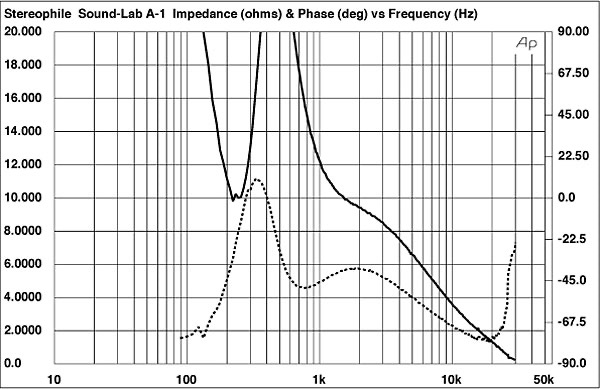
What you showed is the impedance of a woofer, not an electrostatic speaker. Please see post #15 for the example impedance curves of some electrostatic speakers (the impedance curve of the Sound Lab A-1 is shown below). At 30 kHz, this electrostatic speaker is effectively a short (close to 0 Ω). (The impedance of this speaker is about the same as a 5 μF capacitor at ~10 - 20 kHz.) It is a very difficult load for a lot of amplifiers, not just the NC252MP.Could someone explain why electrostat speakers are more likely to have issues when matching with NC252MP?
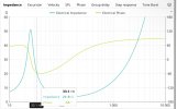
The calculation shown here takes a vertical capacitance into consideration comparing to the baseline model(pure resistive resistor). But to me, it seems that as long as the frequency plugged in is low, the calculated capacitance is gonna be quite large(hundreds of uF), even when Z is larger. For example, a woofer driver with impedance and electrical phase attached below has about 264uF calculated using this method. Following this logic, I don’t really understand why this makes electrostat special.
I’m asking this only out of intellectual curiosity.
But 5uF is low comparing to the calculation I did. I thought this thread is showing that capacitance of speaker driver is a hard load for amp and therefore pure resistor load is not an ideal load to test speaker. But now the impedance/phase graph here shows that at 20k, even though the impedance is very low(lower than 2ohm), but since the frequency is very high, the capacitance is still low(less than 5uF) comparing to the calculation I did on that dynamic woofer driver.What you showed is the impedance of a woofer, not an electrostatic speaker. Please see post #15 for the example impedance curves of some electrostatic speakers (the impedance curve of the Sound Lab A-1 is shown below). At 30 kHz, this electrostatic speaker is effectively a short (close to 0 Ω). (The impedance of this speaker is about the same as a 5 μF capacitor at ~10 - 20 kHz.) It is a very difficult load for a lot of amplifiers, not just the NC252MP.
The phase difference is also tough. The current leads the voltage, which it doesn't do with a pure resistive load.But 5uF is low comparing to the calculation I did. I thought this thread is showing that capacitance of speaker driver is a hard load for amp and therefore pure resistor load is not an ideal load to test speaker. But now the impedance/phase graph here shows that at 20k, even though the impedance is very low(lower than 2ohm), but since the frequency is very high, the capacitance is still low(less than 5uF) comparing to the calculation I did on that dynamic woofer driver.
If the point is just low impedance implies hard load, then aren’t we back to the original spot that more resistor value of load need to be chosen to test a amp?
Or maybe the model including only a vertical capacitor is still an oversimplification and thus doesn’t imply much about the situation?
Hi, I can send you my Nilai stereo for testing that you can torture test for about a month. Drop me a PM. I an curious to see how 19-20khz imd or higher than 1khz fft would look like under different loads.The same I can say about the Nilai
BTW, 4R7//2.2uF to 4R7//33uF is no especially difficult load at 1kHz as a test tone. Any amp should be able to pass it and any good class AB amp passes it. What it in fact tests is a FB stability, loopgain design.
View attachment 292374
Correct me if I’m wrong but to me that test only shows that the power capability does not change with capacitive resistor, it’s not showing anything about SINAD getting worse or staying at the same level right?M33 = M23: Link
Are you saying that different implement(with different PSU) will result in different capability of handling capacitive loads? So does this mean that capacitive load will put more pressure on psu, so “bigger” psu will in some sense alleviate the problem?Correct.
But not all Purifi implementations will behave the same way. See, for example, the PSU section of the T+A M200.
If you did, it would likely change the frequency response of the speakers.I don’t know much, but I am curious. If you were to add a second filter after the feedback loop, could you lesson or stop the oscillations from the add’l capacitance of the revised load (4 ohm//2.2 uF)?
The required compensation will be different for every model of loudspeaker, and I don’t think that it will correspond with the amp output filter.Even if the filter is set high? Similar to what’s already used in the amp? Say 12 dB/ octave at 50kHz?
An unplanned oscillation may damage tweeters if they actually are able to attempt to play the frequency. I think it's a long shot if it's way beyond their normal operating range.
Forgive if this was answered in a much later page, butThe point was that class D amps are always oscillating in ultrasonic range. We don't hold that against them because the frequency is so high. And level very low relative to max power.
Huge number of class d amps are sold in both consumer and professional spaces. No reports have come of any such problems. There is natural roll off in speakers at these frequencies.- 1.7 volts!?! That might not fry all tweeters instantly however it's not insignificant.
And almost all (normal) content has a strong downwards slope from the middle frequencies to the highest frequencies, so there is a lot less musical energy being put into the system.There is natural roll off in speakers at these frequencies.
Again, what you are seeing is how the amp damps the oscillation starting up. It has to do this with every iteration so it looks like an oscillation.I don’t know much, but I am curious. If you were to add a second filter after the feedback loop, could you lesson or stop the oscillations from the add’l capacitance of the revised load (4 ohm//2.2 uF)?
Huge number of class d amps are sold in both consumer and professional spaces. No reports have come of any such problems. There is natural roll off in speakers at these frequencies.
there's simply no recorded evidence that Class D is damaging anything.
I find it amazing that in a forum where surely many would feel an Apple dongle is inadequate and worship some Topping DAC or AHB2 amp etc with S/N of 120 dB, that so many say 1.7V is irrelevant. Please note I am NOT saying it is a problem...but it seems hypocritical to diss a dongle whose performance is most likely 99% transparent to 99% of the people with 99% of the music-and then dismiss the 1.7V etc as negligible.42 pages and this conversation is still going on about a thing that's of no concern??