• WANTED: Happy members who like to discuss audio and other topics related to our interest. Desire to learn and share knowledge of science required. There are many reviews of audio hardware and expert members to help answer your questions. Click here to have your audio equipment measured for free!

Will AIYIMA A07 work with 4ohm//2.2uF load? - Test and measurements

pma

Major Contributor
Joined
Feb 23, 2019
Messages
4,602
Likes
10,768
Location
Prague
Will AIYIMA A07 work with 4ohm//2.2uF load? - Test and measurements

You might get surprised :) (or maybe not, those who are knowledgeable). In my latest test thread, I have shown how the Hypex NC252MP failed to drive 4ohm in parallel with 2.2uF load, the load simulating some of the electrostatic speakers that are difficult to drive. So how about the tiny little AIYIMA A07? Let's test it with this load. All the measurements have been done again with 4ohm//2.2uF load, AIYIMA was supplied from 48Vdc power supply (my own design, 10A capability), measurement bandwidth was 22Hz-22kHz to keep it comparable with NC252MP test and to prevent objections on inaudibility of anything above this. Here we go:

1. Output noise voltage
A07_4R+2.2uF_noise.png

Output noise voltage of A07 with this load is 298.6uV/BW22kHz.

A small reminder to the same test with NC252MP NC252MP_4R+2.2uF_noiseV.png well, it was 20.45mV under same conditions. 68x worse.


2. SINAD at 5W/1kHz
A07_4R+2.2uF_THDN1kHz_5W.png

This plot must not be omitted at ASR. The SINAD result is 83.9dB.

Again a small reminder to the same test with NC252MP NC252MP_4R+2.2uF_5W-1k.png 47.9dB, worse by 36dB than A07, 63x.


3. THD+N vs. power at 1kHz
A07_NC252MP_4R+2.2uF_THDN1kHz_power.png

The plots show direct comparison of AIYIMA A07 and NC252MP under same test conditions.


4. THD+N vs. frequency at 22W(4ohm) power
A07_4R+2.2uF_THDNfreq_22W.png

Please note that as measuring BW is 22kHz, the plot above 11kHz shows noise only, for distortion it is pointless above 11kHz.
Note: when tetsed at 44W into this load, the amp switched off itself near to 17kHz
A07_4R+2.2uF_THDNfreq_44W.png


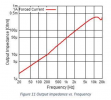
5. Frequency response into 4ohm//2.2uF
A07_4R+2.2uF_freqresp_22W.png

No surprise, +1.1dB at 10kHz and +2.2dB at 20kHz. The 2.2uF capacitor is directly added to the A07 output LC filter

6. Conclusion

Maybe surprisingly to some readers, AIYIMA A07 passed the test without any bigger problems. The rise of frequency response at the upper end is easily understandable and similar to increasing of resistive load. The limited power at very high frequencies is again understandable as a current protection action. All in all, A07 can be operated with electrostats without severe degradation of parameters.
Much better result compared to NC252MP is due to circuit principle. A07 uses LC filter out of the feedback loop, so its function is not affected other than FR peaking at high frequencies. In case of NC252MP, the load capacitance dramatically changes switching and oscillating condition in the feedback of the amp, thus it fails to work properly.
 

IAtaman

Major Contributor
Forum Donor
Joined
Mar 29, 2021
Messages
2,383
Likes
4,098
You can test 4ohm in paralel with a toaster to see if that works fine if you like, but I believe the validity of the test as a predictor of real life performance is yet to be proven. And I am not referring to the audibility or rarity of estatsm, I mean as an engineering concept, is 4ohm paralel with 2.2uF capacitor a realitic model of a speaker load an amp might face in real life.
 

MaxwellsEq

Major Contributor
Joined
Aug 18, 2020
Messages
1,707
Likes
2,556
There are now three data points for this test:
1. Class AB with linear PSU = satisfactory
2. NC252MP with SMPS = unsatisfactory
3. AIYIMA A07 with proprietary PSU = satisfactory

Does an out of the box AIYIMA A07 PSU work ok? Because all the PSUs are different, it's difficult to confirm there is a control in the excitement.
 

IAtaman

Major Contributor
Forum Donor
Joined
Mar 29, 2021
Messages
2,383
Likes
4,098
Here is article on Large-Signal Equivalent-Circuit Model of Asymmetric Electrostatic Transducers.

If I am understanding it correctly, the article seems to argue that a linearized modelling of an electrostatic transducer with a linear resistor and a parallel capacitor can not be used accurately to predict power consumption and distortion, and is offering a more complex large signal modelling. Clearly there are a quite a few people around here who are a lot more qualifed to make an assessment including pma, would be interested to understand what is their view on the topic.
 

Sokel

Master Contributor
Joined
Sep 8, 2021
Messages
6,037
Likes
6,056
You can test 4ohm in paralel with a toaster to see if that works fine if you like, but I believe the validity of the test as a predictor of real life performance is yet to be proven. And I am not referring to the audibility or rarity of estatsm, I mean as an engineering concept, is 4ohm paralel with 2.2uF capacitor a realitic model of a speaker load an amp might face in real life.
Aren't the parallel electrodes of an electrostatic speaker look a little like a capacitor?Do they form one?
In theory yes,so it's a lot to search,it's not as simple as to diminish everything with the thought "it plays so it's ok".
 

IAtaman

Major Contributor
Forum Donor
Joined
Mar 29, 2021
Messages
2,383
Likes
4,098
Aren't the parallel electrodes of an electrostatic speaker look a little like a capacitor?Do they form one?
In theory yes,so it's a lot to search,it's not as simple as to diminish everything with the thought "it plays so it's ok".
They do look like caps and they seem to be modeled as caps as well. One question, for example, is whether they can be modeled accurately as a single value capacitor across the whole frequency range. When they are working, the diaphram is supposed to move, effectively changing the shape of the "capacitor". This has no impact? I understand electromagnetic speakers are modeled by a relatively complex network or caps, resistors and inductors. Are we sure a single resistor and a parallel cap is good enough to model an eletrostat? Or maybe asked more precisely, is the 4ohm/2.2uF load a realistic model of a load for a power amp. The article I shared seemed to suggest not. I was hoping to get some comments from someone who knows more than me to understand better.
 

ahofer

Master Contributor
Forum Donor
Joined
Jun 3, 2019
Messages
5,023
Likes
9,073
Location
New York City
Here is article on Large-Signal Equivalent-Circuit Model of Asymmetric Electrostatic Transducers.

If I am understanding it correctly, the article seems to argue that a linearized modelling of an electrostatic transducer with a linear resistor and a parallel capacitor can not be used accurately to predict power consumption and distortion, and is offering a more complex large signal modelling. Clearly there are a quite a few people around here who are a lot more qualifed to make an assessment including pma, would be interested to understand what is their view on the topic.
Can someone fill me in on how close/far it is for a conventional speaker design and what we might see in the speaker resistance measurements that would indicate potential conditions similar to this load?
 
D

Deleted member 48726

Guest
They do look like caps and they seem to be modeled as caps as well. One question, for example, is whether they can be modeled accurately as a single value capacitor across the whole frequency range. When they are working, the diaphram is supposed to move, effectively changing the shape of the "capacitor". This has no impact? I understand electromagnetic speakers are modeled by a relatively complex network or caps, resistors and inductors. Are we sure a single resistor and a parallel cap is good enough to model an eletrostat? Or maybe asked more precisely, is the 4ohm/2.2uF load a realistic model of a load for a power amp. The article I shared seemed to suggest not. I was hoping to get some comments from someone who knows more than me to understand better.
This is a totally valid and relevant question in the lights of this topic that has risen. Surely there are some circuit gurus on ASR that can chime in?
 
OP
pma

pma

Major Contributor
Joined
Feb 23, 2019
Messages
4,602
Likes
10,768
Location
Prague
The reason why Ncore switching frequency and stability is grossly affected by high load capacitance should be clear from its principle schematics. It is a self-oscillating circuit with phase-shift control using the reconstruction filter L1,C1 and phase lead network R3,C2. The frequency of the self oscillations would be at the point where loop gain phase shift is 180°. Addition of 2.2uF capacitor to C1 changes the FB oscillation conditions significantly.
Contrary to this, the AIYIMA A07 TPA3255 uses independent oscillator to define switching frequency. But, it has output LPF filter, LC, outside the FB loop - so it is stable even after connecting the 2.2uF capacitance. Both is a double edged sword - you get better stability at the expense of frequency response modulated by load complex impedance or vice versa.

Back to A07 topic - measured frequency response into 4ohm//2.2uF up to 50kHz. One positive effect - better attenuation of class D HF garbage.

A07_4R+2.2uF_freqresp_45kHz.png

What we can see is simply LC filter peaking with 4ohm//2.2uF load. Completely predictable and can be easily simulated for any load.


... and THD+N vs. power into 4ohm//2.2uF at 22Hz, 1kHz and 5kHz, @22kHzBW
A07_4R+2.2uF_THDN_22-1k-5k_power.png


CCIF IMD 19+20kHz into 4ohm//2.2uF at 9Vrms output voltage
A07_4R+2.2uF_CCIF_9V.png

It is not that bad, difference tone 1kHz is attenuated by 90dB, odd harmonics skirts start around -60dBr and are quite quickly attenuated.
 

LTig

Master Contributor
Forum Donor
Joined
Feb 27, 2019
Messages
5,814
Likes
9,530
Location
Europe
Aren't the parallel electrodes of an electrostatic speaker look a little like a capacitor?Do they form one?
In theory yes,so it's a lot to search,it's not as simple as to diminish everything with the thought "it plays so it's ok".
Electrostatic drivers are not driven directly but through a transformer which I think does not work perfectly far above the audio range and hence does not transform the capacitance to the power amp at those higher frequencies. This may be the reason why people report no problems feeding such speakers with class D power amps.
 

LTig

Master Contributor
Forum Donor
Joined
Feb 27, 2019
Messages
5,814
Likes
9,530
Location
Europe
The reason why Ncore switching frequency and stability is grossly affected by high load capacitance should be clear from its principle schematics. It is a self-oscillating circuit with phase-shift control using the reconstruction filter L1,C1 and phase lead network R3,C2. The frequency of the self oscillations would be at the point where loop gain phase shift is 180°. Addition of 2.2uF capacitor to C1 changes the FB oscillation conditions significantly.
Didn't know this. Maybe one should add a zobel network (a resistor and a coil in parallel) in series with the output, similar to class AB power amps, to decouple the feedback network from the output at higher frequencies. Do you think you could give this a try, or will this not work?
 

Hapo

Senior Member
Joined
Jan 11, 2022
Messages
464
Likes
321
...this thread isn't getting much traction...

...maybe I should cancel my Buckeye Amp order...???...I already have one of these...!!!...
 

DavidMcRoy

Addicted to Fun and Learning
Joined
Jul 10, 2018
Messages
576
Likes
997
Anecdotally: I have driven my vintage c. 1990s Acoustat SPECTRA 1100s with an Aiyima A07 at moderate but satisfying levels with no complaints from the amplifier. The Acoustat's electrostatic panel approaches 0 ohms at 20kHz when its HF EQ switch is in the highest (maximally flat response) position. I didn't see a rising response, but there's a lot going on in that speaker: a transformer, etc.
 
Last edited:

jimk1963

Member
Joined
Mar 20, 2023
Messages
78
Likes
107
Main point of @pma results here is (as he stated) - when you look at the schematic of these Class D's, they need an LC lowpass filter at the output in order to filter out all the above-audio range tones/noise associated with these oscillating-based designs. There are options - one option is to place the output LC network within the Class D's feedback path. Another option is to connect the feedback prior to the output filter. This high-capacitive load test seems to expose which architecture the amp is based on. Is that helpful to know? Could be.

One thing I do find curious though, is that from reading Bruno's and others' design articles where LC-inside-the-loop are discussed, this approach seems to accomplish both (a) desensitization of the LC filter component tolerances (a good thing) and (b) achieves a crazy-low output impedance in the micro-ohms (another good thing). Bruno talks about the Purifi design on this thread, and the thread includes a plot of this low low output impedance.


So it's curious that the high-capacitance load causes so much undoing of the NC252MP's feedback loop behavior. Seems as though this is enough capacitance to actually cause changes in loop gain/phase margins and subsequently upset the self-oscillation frequency - leading to noise that gets aliased down to baseband (audio) frequencies, and unforeseen spurious rise.

Is the NC252MP feedback not "sufficient" to overcome this? Purifi's amp claims to have 20 dB higher loop gain (75 dB vs. 55 dB), from Bruno's comments in that diy thread:

"So what's new in this amplifier? One thing is that I've developed a sampled domain model for self-oscillating loops that remains valid for all duty cycles, so it can predict closed loop response exactly under all conditions. This then allows finding a loop design that has very high loop gain (about 75dB at 20kHz, which is 20dB better than my previous designs) without running into stability problems near clip. A design procedure like this can't be patented because you can't prove that someone has been using it, so in a break from past style I'm not going to publish any details of this mathematical model. It's a trade secret, plain and simple."

Does the Purifi then not suffer issues with this high-capacitance load? Not necessarily a "real world" concern with vast majority of speakers being much tamer than this stress-load, but still interesting to find out.
 

Attachments

  • Screenshot 2023-04-19 190458.png
    Screenshot 2023-04-19 190458.png
    78.6 KB · Views: 51

MaxwellsEq

Major Contributor
Joined
Aug 18, 2020
Messages
1,707
Likes
2,556

So it's curious that the high-capacitance load causes so much undoing of the NC252MP's feedback loop behavior. Seems as though this is enough capacitance to actually cause changes in loop gain/phase margins and subsequently upset the self-oscillation frequency - leading to noise that gets aliased down to baseband (audio) frequencies, and unforeseen spurious rise.

Is the NC252MP feedback not "sufficient" to overcome this? Purifi's amp claims to have 20 dB higher loop gain (75 dB vs. 55 dB), from Bruno's comments in that diy thread:
A key statement from Bruno in the above linked post is:

"Then there is the loop structure that allows better control of the closed loop frequency response. My previous amp* has approximately a 1st order roll-off. Now, since the output filter naturally has a second order roll-off it means that this amp could be overdriven with out of band noise from e.g. DSD recordings (in fairness, only when you cranked a quiet recording high)."
 

TwoEyedJack

Member
Joined
Jun 2, 2022
Messages
37
Likes
12
The reason why Ncore switching frequency and stability is grossly affected by high load capacitance should be clear from its principle schematics. It is a self-oscillating circuit with phase-shift control using the reconstruction filter L1,C1 and phase lead network R3,C2. The frequency of the self oscillations would be at the point where loop gain phase shift is 180°. Addition of 2.2uF capacitor to C1 changes the FB oscillation conditions significantly.
Contrary to this, the AIYIMA A07 TPA3255 uses independent oscillator to define switching frequency. But, it has output LPF filter, LC, outside the FB loop - so it is stable even after connecting the 2.2uF capacitance. Both is a double edged sword - you get better stability at the expense of frequency response modulated by load complex impedance or vice versa.

Back to A07 topic - measured frequency response into 4ohm//2.2uF up to 50kHz. One positive effect - better attenuation of class D HF garbage.

View attachment 274955
What we can see is simply LC filter peaking with 4ohm//2.2uF load. Completely predictable and can be easily simulated for any load.


... and THD+N vs. power into 4ohm//2.2uF at 22Hz, 1kHz and 5kHz, @22kHzBW
View attachment 274957


CCIF IMD 19+20kHz into 4ohm//2.2uF at 9Vrms output voltage
View attachment 274958
It is not that bad, difference tone 1kHz is attenuated by 90dB, odd harmonics skirts start around -60dBr and are quite quickly attenuated.


Is this guy right here experiencing a result of what you are describing in your tests ? His speakers are the DIY C-notes and the amp the A07, he has a similar increase above 10khz as the one you show here.
 

abdo123

Master Contributor
Forum Donor
Joined
Nov 15, 2020
Messages
7,444
Likes
7,954
Location
Brussels, Belgium
@pma Do you think you can find sometime to test if the A7 can be used in bridged configuration with a 4ohm load? I have two amps lying around that i would like to use for some passive subwoofers.
 
  • Like
Reactions: MCH
Top Bottom