• WANTED: Happy members who like to discuss audio and other topics related to our interest. Desire to learn and share knowledge of science required. There are many reviews of audio hardware and expert members to help answer your questions. Click here to have your audio equipment measured for free!

Why 12 power transistors in a class AB (?)120 W (?) amplifier?

OP
DanielT

DanielT

Major Contributor
Joined
Oct 10, 2020
Messages
4,805
Likes
4,731
Location
Sweden - Слава Україні

This is just wrong. You can neither damage the rectifier, nor the transformer by increasing the capacitance.
Ok! Please note that my post consisted partly of a verification of what Doodski said, which I thought was true plus a question about Transformer and not a statement.:)

One thing is starting to become more and more obvious.

I get that: Audio power amplifier design by Douglas Self and read on. It is available as a pdf online, I will investigate whether that version is at a not too high theoretical level. If it works for me, I'll buy that book.:)
 
Last edited:

pseudoid

Master Contributor
Forum Donor
Joined
Mar 23, 2021
Messages
5,167
Likes
3,504
Location
33.6 -117.9
Some (old) EEs and/or tube fanatics can look at a tube and tell you that it is a KT88 and not a 6550, from 6 feet away.
The J. Geils Band used to “First Look at the Purse”.
202110_NPNgain.jpg

@pseudoid was trained to first look at the “hFE”...
 

sarumbear

Master Contributor
Forum Donor
Joined
Aug 15, 2020
Messages
7,604
Likes
7,321
Location
UK
Saurbear, please note that my post consisted partly of a verification of what Doodski said, which I thought was true plus a question about Transformer and not a statement.
I was simply trying to tell you that what you read is wrong. A rectifier on mains AC creates a 100Hz pulsating voltage (120Hz in US). This means the voltage has 10ms to rise from zero to full. Both the transformer and the rectifier has ample time to respond while the capacitor is charged. Besides, once the capacitor is charged the capacitor is simply ripple charged.
 
Last edited:

solderdude

Grand Contributor
Joined
Jul 21, 2018
Messages
16,004
Likes
36,222
Location
The Neitherlands
There is a big rectifier in there. It can handle some current.
During start-up the current will be limited by the transformer.
When capacitance becomes too large there could be a too long series of charge pulses the rectifier may not like.
Just don't overdo it in capacitance. That transformer inside can deliver quite some current.
You can increase capacitance safely to 6,800uF.... maybe upto 10,000uF but would advice against going much higher.
You can always increase the voltage rating. This may prolong the lifespan a bit.
 

Doodski

Grand Contributor
Forum Donor
Joined
Dec 9, 2019
Messages
21,543
Likes
21,832
Location
Canada
I was simply trying to tell you that what you read is wrong. A rectifier on mains AC creates a 100Hz pulsating voltage (120Hz in US). This means the voltage has 10ms to rise from zero to full. Both the transformer and the rectifier has ample time to respond while the capacitor is charged. Besides, once the capacitor is charged the capacitor is simply ripple charged.
I'm getting mixed messages from important people that have a significant education in electronics. Firstly I was advised in strong terms by my electronics theory instructors to not go too far increasing the filter capacitor(s) because the bridge will fail. Then I have @sarumbear whom has a very significant education in electronics advising the opposite and of course @solderdude has contributed to this too. If the terms of the capacitor swap/increase where the same or similar with all peeps then I would go with the flow and not concern myself with a bridge blowing but I am getting mixed messages from people with a higher education. Perhaps this is worthy of a thread for this topic because this topic comes up maybe every 4-5 months.
 

sarumbear

Master Contributor
Forum Donor
Joined
Aug 15, 2020
Messages
7,604
Likes
7,321
Location
UK
I'm getting mixed messages from important people that have a significant education in electronics. Firstly I was advised in strong terms by my electronics theory instructors to not go too far increasing the filter capacitor(s) because the bridge will fail. Then I have @sarumbear whom has a very significant education in electronics advising the opposite and of course @solderdude has contributed to this too. If the terms of the capacitor swap/increase where the same or similar with all peeps then I would go with the flow and not concern myself with a bridge blowing but I am getting mixed messages from people with a higher education. Perhaps this is worthy of a thread for this topic because this topic comes up maybe every 4-5 months.
What some are saying that if you use humangous capacitor like a few tens of Farads (many thousands times larger than we are talking here) you may have issues. They are simply confusing people with silly remarks that doesn't relate to the real world. You cannot find or fit a substantially higher value capacitor then you have now to replace what you have. Don‘t worry.
 

solderdude

Grand Contributor
Joined
Jul 21, 2018
Messages
16,004
Likes
36,222
Location
The Neitherlands
Yep, a factor 1.5 or 2 capacitance increase usually doesn't give issues. Certainly not with the beefy BR on the picture.
There's limits to CU product sizes anyway.
Increasing capacitance after a SMPS or certain regulators may well not be the best idea.
 

tomtoo

Major Contributor
Joined
Nov 20, 2019
Messages
3,712
Likes
4,777
Location
Germany
How much did that weigh and how much power did it produce?

I was simply trying to tell you that what you read is wrong. A rectifier on mains AC creates a 100Hz pulsating voltage (120Hz in US). This means the voltage has 10ms to rise from zero to full. Both the transformer and the rectifier has ample time to respond while the capacitor is charged. Besides, once the capacitor is charged the capacitor is simply ripple charged.

And how do you know to switch on at zero crossing?
 

RayDunzl

Grand Contributor
Central Scrutinizer
Joined
Mar 9, 2016
Messages
13,247
Likes
17,162
Location
Riverview FL
How much did that weigh and how much power did it produce?

"The MRAs come in wooden crates and weigh in at 683 pounds each not counting the crates."


"The Master Reference Amplifier brings a new level of performance to sound reproduction. Its tremendous power (exceeding 1,000 W into 8 Ohms, 2,000 W into 4 Ohms, 4,000 W into 2 Ohms, 8,000 W into 1 Ohm, and 16,000 W into .5 Ohm) gives the listener the freedom to enjoy unconstrained sound reproduction. The technological innovations that manage these large amounts of power are transparent to the user."

 
OP
DanielT

DanielT

Major Contributor
Joined
Oct 10, 2020
Messages
4,805
Likes
4,731
Location
Sweden - Слава Україні
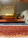
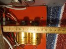
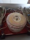
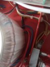
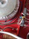
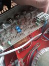
The discussion maximum value of new electrolytes. I'm not getting into that. You with more experience and knowledge can discuss that.In practical terms, the space provides physical limitations, see photos. The electrolytes are screwed on (I guess I can, I'll have to remove the black screw and check).

As can be seen in the pictures, there is still some leeway. If new holes need to be screwed into the plate they are in, I will do it.

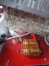
Two electrolytes (or it is called electrolytic capacitors) at each channel now .. Could four smaller type 50V 4700UF per channel be something (if there is physical space)? I googled and that particular combination seems to be common among electrolytes.In any case, I have to check it out. Then calm in the storm, I am inexperienced but not really that stupid that I do this entirely myself. I take the amplifier to my friend who has experience of changing electronics in amplifiers. So we will change the electrolytes. He was the one who made this change:


We'll see what happens. First we measure it well and see what it looks like on the occiloscope. I actually do not know what kind of measuring equipment he has, if he can measure distortion levels for example. I can check it with him.
He probably puts some dummy load in there and sees when it clipps. Maybe if he can see square waves. I actually do not know because I have not engaged in such measuring instruments myself. He has a small hobby workshop with various things, so it will be good.:)
 

Attachments

  • IMG_20211027_075459 (2).jpg
    IMG_20211027_075459 (2).jpg
    248.7 KB · Views: 70
  • IMG_20211027_075421 (2).jpg
    IMG_20211027_075421 (2).jpg
    231.9 KB · Views: 72
Last edited:

solderdude

Grand Contributor
Joined
Jul 21, 2018
Messages
16,004
Likes
36,222
Location
The Neitherlands
Could four smaller type 50V 4700UF per channel be something

When your amp's power supply is below +/- 40V yes.
When it is around 50V I would recommend at least 63V.
Two caps in parallel can have a lower ESR than 1 cap of the same total value.
Given that the original amp had only 2 'normal' smoothing caps a super low ESR does not seem to be a requirement.

Two electrolytes (or it is called electrolytic capacitors)

Electrolyte is the fluid inside a 'wet' electrolytic capacitor
'Dry' electrolytes also exist but the ones you are going to replace are wet and is old enough to be almost dried out by now.
 
OP
DanielT

DanielT

Major Contributor
Joined
Oct 10, 2020
Messages
4,805
Likes
4,731
Location
Sweden - Слава Україні
Thanks for the information Solderdude. :)

Another aspect, which is more of a theoretical question,what adds really large electrolytic capacitors?

The reason I ask is because I have heard those who say that it makes sense to have a large "bank" to be able to pick up and take out when needed (at transient peaks, I suspect ..?) But I have also read that it is a myth that a large "bank" in itself does not add any better performance. I can imagine that it depends on a lot of factors that determine if a large bank is positive,? Probably too big a question to sort out in this thread. Also, I have no schedule on the amplifier. I guess it's difficult to give an answer specifically regarding this amplifier, my guess.Large bank better quality , performance Sela amp that is.

It is rather pointless for me to buy a large nice electrolytic capacitor if it does not add anything positive to the sound. But on the other hand, to be honest, this is about learning and making it work at least as interesting for me anyway. Besides, electrolytic capacitors are not that expensive, I think.:)

It may cost a little if you want to have fun. But it's worth it to me anyway.:)
 
Last edited:

pma

Major Contributor
Joined
Feb 23, 2019
Messages
4,602
Likes
10,769
Location
Prague
You need to find a compromise. Too large bank means very high charging current with high current peaks = more interference radiated.
Better way is to design an amp for high PSR. Too large bank is a band aid for a poor design.
 
OP
DanielT

DanielT

Major Contributor
Joined
Oct 10, 2020
Messages
4,805
Likes
4,731
Location
Sweden - Слава Україні
Info transformer. This is written on it:

Made by Transduktor Sweden. TRANSF. NO. 6964
V 8448
 

Attachments

  • IMG_20211027_111810 (1).jpg
    IMG_20211027_111810 (1).jpg
    126.8 KB · Views: 74
  • IMG_20211027_113330 (1).jpg
    IMG_20211027_113330 (1).jpg
    159.8 KB · Views: 75
  • IMG_20211027_113341 (1).jpg
    IMG_20211027_113341 (1).jpg
    182.6 KB · Views: 76
  • IMG_20211027_113357 (1).jpg
    IMG_20211027_113357 (1).jpg
    207.3 KB · Views: 76
  • IMG_20211027_113410 (1).jpg
    IMG_20211027_113410 (1).jpg
    234.4 KB · Views: 84

solderdude

Grand Contributor
Joined
Jul 21, 2018
Messages
16,004
Likes
36,222
Location
The Neitherlands
Ah so it is 2 bridge rectifiers each having 2 reservoir caps and relatively long wires to the amp (making low ESR even less important) connected to a common transformer.

This rectifier should have no issues with charging those reservoir caps even when the capacitance is doubled or somewhat increased.
When the designer would have thought it needed more capacitance he probably would have put in larger ones or doubled the amount.

Decoupling seems to rely on smaller caps on the amplifier board.
 

sarumbear

Master Contributor
Forum Donor
Joined
Aug 15, 2020
Messages
7,604
Likes
7,321
Location
UK

DonH56

Master Contributor
Technical Expert
Forum Donor
Joined
Mar 15, 2016
Messages
7,880
Likes
16,667
Location
Monument, CO
To echo the rest, I would choose the same or slightly higher capacitance value, same or higher voltage rating, and the same or higher temperature rating. Temperature is a significant factor in capacitor lifetime. You can typically find 85 degC, 105 degC, and 125 degC with increasing cost. I would not worry about ESR, ESL, or other parasitics since they are (a) likely to be similar among similar electrolytic caps like these and (b) chances are the power supply won't care much. ESR/ESL is much more important (critical) for switch-mode power supplies and high-frequency decoupling (the latter should be handled by the smaller caps anyway).

Failing supply caps will add hum and buzzing in the output typically seen at 120 Hz and harmonics from a bridge rectifier. If you are already in there, replacing the bulk electrolytic caps is probably easy and fairly cheap insurance. Use a good name brand.

FWIWFM - Don
 

tomtoo

Major Contributor
Joined
Nov 20, 2019
Messages
3,712
Likes
4,777
Location
Germany
Top Bottom