• WANTED: Happy members who like to discuss audio and other topics related to our interest. Desire to learn and share knowledge of science required. There are many reviews of audio hardware and expert members to help answer your questions. Click here to have your audio equipment measured for free!

White noise, clipping and upsampling DAC effects.

Blumlein 88

Grand Contributor
Forum Donor
Joined
Feb 23, 2016
Messages
20,759
Likes
37,612
http://audiosciencereview.com/forum...ements-of-mytek-brooklyn-dac.1828/#post-46082

Ray was looking at a test signal I suggested for the Mytek Brooklyn review thread starting with the above post.

It is a test signal Juergen Reis of MBL suggested to JA of Stereophile. It is - 4dbFS of white noise played at a lower sample rate and measured at a much higher sample rate. The idea is the residual noise above nyquist of the original signal will reveal the shape/steepness of the anti-imaging filter on the DAC output.

Ray upsampled such a signal by 8x to better see the waveshape between samples as I had mentioned such a signal clipped an ADC at lower levels than a -.1 dbFS sine wave. Ray surmised these were intersample overs which seems reasonable. A question in my mind was whether such signals were showing us accurately the imaging filter shape or was it ultrasonic noise from the slight clipping. In upsampled signals the level of ultrasonic noise was higher if the original was -4 db FS than if it was -6 db FS by a pretty large amount. The ultrasonic noise was very high for a 0 dbFS white noise signal when upsampled. Now all of this was in software I should mention. Another question was whether upsampling playback software clipped such signals.

Some DACs have been known to have inadequate analog headroom for intersample overs and to have some clipping from that. I suspect that is why Reis chose - 4db as most well designed gear is not going to have an issue with a signal at that level in the analog output stage.

So I used an old Tact RCS 2.0 set unity gain to playback these signals at 48 khz, and recorded them at 192 khz with a Focusrite Forte. I should mention this is 93.9 on the Tact volume control as it applies digital gain above that level up to 99.9 settings. So this is no digital volume adjustment. I set input levels as high as possible on the Forte ADC as long as it did not indicate clipping. I had signals starting at 0 dbFS and going in 1 db steps to -7 dbFS.

To shorten the story, I found the intersample levels not to cause any clipping in the DAC done this way and the resulting FFT does appear to show the shape of the anti-imaging filter of the DAC. Also I found if I adjusted levels so that - 4db was also nearly, but not clipping the ADC input, the resulting noise profile was virtually identical to 0 db. Without resetting gain the shape of the response was the same at all levels other than being lower by 1 db each progression thru the test signal.

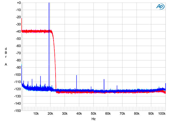
Here is the shape of the 0 dbFS noise signal in red, the gain adjusted - 4dbFS signal in green, and the silent noise floor in blue.

0minus4 tact.png

Here is the same comparison using a Focusrite 18i20 interface in place of the Tact.
0minus4 18i20.png


Here is a comparison of the Tact and the Focusrite 18i20 on the 0 dbFS noise signal. You can see the 18i20 interface has a bit steeper filter and the noise presumably from the sigma delta process starts at lower frequencies.

0db tact 18i20.png


Next I used upsampling in the playback software to play the 48 khz file at 96 khz using the Focusrite 18i20. You see the ultrasonic noise level is elevated when software upsampled. Shown is 0 dbFS in red, -4 dbFS in green and -6 dbFS in blue. It appears by -6 db the effect is gone. This pretty well mirrors what upsampling in offline software was showing.
upsampled.png


I also notice it this causes mirroring of the below 24 khz range at a lower level one more 24 khz band before rolling off. Is this why upsampling can sound different? The ultrasonic noise is not so far down in level as you get near 0 dbFS. I would think it can image back down into the below 20 khz band. Were it a transient, and no white noise existed there it could possibly be audible in level. Probably the level would be too low to be heard especially in the midst of other parts of the music. Nevertheless, it is one more good reason NOT to upsample your music upon playback. Instead best fidelity is likely at the native sample rate of the recording.
 

RayDunzl

Grand Contributor
Central Scrutinizer
Joined
Mar 9, 2016
Messages
13,250
Likes
17,191
Location
Riverview FL
Nice.

If I remember correctly, -6.3Dbfs applied to the 48kHz full-scale noise resulted in no clips and like "one" full scale sample in a long file.

Try a -6 vs -7 just to see if there is a last little bit to extract.
 
OP
Blumlein 88

Blumlein 88

Grand Contributor
Forum Donor
Joined
Feb 23, 2016
Messages
20,759
Likes
37,612
Here is -5dbFS, -6dbFS, and -7dbFS in red, green and blue respectively. Upsampled to 96 khz rates during playback. Now I only used 10 seconds for each level. You could generate - 6db levels that would clip a few times upsampled or you might well get plenty that don't. It looks like software upsampling of the signal I tested with shows none at - 6db and shows plenty at all higher levels.

BTW, Don mentioned he thought the crest ratio with pure white noise was 10 db. In the recorded sections of white noise both at 48 khz playback and 96 khz playback I am seeing peak to RMS differences at 10 db give or take a couple tenths.

5 6 and 7 db ups 96 playback.png
 

DonH56

Master Contributor
Technical Expert
Forum Donor
Joined
Mar 15, 2016
Messages
7,894
Likes
16,710
Location
Monument, CO
A delta-sigma DAC (most of them these days) I would expect to exhibit a rising noise floor like you see. When it is flat before meeting the rising curve at -5 dB I think implies it is clipping and thus generating HF content at the DAC's output. The spur over Nyquist is probably clock feedthrough (imaged clock spur).

Maybe...

I am swamped with other stuff or would dig up the theory and practice of various flavors (colors) of noise, sorry to leave you hanging... I spent a lot of time on noise stuff but it was years ago. The noise and jitter I deal with now include Gaussian and white as well as many others but is application-specific (and the application ain't audio).
 
OP
Blumlein 88

Blumlein 88

Grand Contributor
Forum Donor
Joined
Feb 23, 2016
Messages
20,759
Likes
37,612
A delta-sigma DAC (most of them these days) I would expect to exhibit a rising noise floor like you see. When it is flat before meeting the rising curve at -5 dB I think implies it is clipping and thus generating HF content at the DAC's output. The spur over Nyquist is probably clock feedthrough (imaged clock spur).

Maybe...

I am swamped with other stuff or would dig up the theory and practice of various flavors (colors) of noise, sorry to leave you hanging... I spent a lot of time on noise stuff but it was years ago. The noise and jitter I deal with now include Gaussian and white as well as many others but is application-specific (and the application ain't audio).

Thanks Don. The spur at 31 khz is an idle tone in the ADC. The tone is there at the same location whether the ADC is running at 96 khz or 192 khz.

Am I right that since the clipping isn't there at 48 khz, and is when upsampled the DAC itself isn't actually clipping, but the file was clipped so the DAC is putting out what the upsampled digital signal is? Though if the DAC were clipping it would look the same I suppose.
 
Last edited:

RayDunzl

Grand Contributor
Central Scrutinizer
Joined
Mar 9, 2016
Messages
13,250
Likes
17,191
Location
Riverview FL
Am I right that since the clipping isn't there at 48 khz, and is when upsampled the DAC itself isn't actually clipping, but the file was clipped so the DAC is putting out what the upsampled digital signal is? Though if the DAC were clipping it would look the same I suppose.

Maybe you are seeing some analog headroom...

Experiment:

Create full scale 96kHz 12kHz sine.

Delete first sample time. (Shifts the wave left one half of 48kHz sample time)

Downsample to 48kHz. Sample values change, but it is still a valid 12kHz sine, and Audacity is foolish enough to think those values can be amplified by 3dB without "clipping".

Amplify digitally till clipping is seen in analog output.

upload_2017-8-4_21-19-59.png
 
Last edited:

DonH56

Master Contributor
Technical Expert
Forum Donor
Joined
Mar 15, 2016
Messages
7,894
Likes
16,710
Location
Monument, CO
Well, I think I wrote too hastily when I suggested clipping, and did not read the thread well enough to see what you were doing. I am sorry, my bad (insanely busy day).

Upsampling interpolates between samples, estimating what those new samples might rightly be. These days I'd be very surprised if it was simply linear interpolation; I would expect a complex polynomial or sinusoidal based algorithm. With noise as an input, I suspect those "flat" regions are the result of the algorithm attempting to predict where the noise would go, and that will effectively create a noise image up to the second (new) Nyquist region. E.g. if you interpolate a noise signal sampled at 48 kS/s up to 96 kS/s, then I'd expect a noise image would fill in the region from 24 kHz to 48 kHz, and I think that is happening (? - having trouble seeing the plot axes). Not clipping, but a consequence of interpolation trying to fill in noise (GIGO). With upsampling there is always the question of how accurately it is estimating the new higher-frequency signal content derived from the waveforms sampled at the lower rate.

I am not used to seeing idle tones these days; modern converters are complex enough that true idle tones rarely occur. I still wonder if it is from some source of signal leakage but do not know. For those who are curious, the hand-waving explanation of idle tones is that, since the filter length in the delta-sigma converter (ADC or DAC) is finite, then the right signal level will cause codes (bits, data words) in the filter to "loop" and repeat endlessly, generating a spurious idle tone. This was a big problem in the early days of low-order modulators (or demodulators) and also mucked up the use of delta-sigmas in DC applications (like multimeters). Dither and higher-order loops have pretty much made that a non-issue for many years now. A little noise in the loop "breaks up" the idle tones by making the codes through the filter vary a little bit so it no longer endlessly repeats.

FWIWFM (not much, brain only firing on a single cylinder today) - Don
 
OP
Blumlein 88

Blumlein 88

Grand Contributor
Forum Donor
Joined
Feb 23, 2016
Messages
20,759
Likes
37,612
Maybe you are seeing some analog headroom...

Experiment:

Create full scale 96kHz 12kHz sine.

Delete first sample time. (Shifts the wave left one half of 48kHz sample time)

Downsample to 48kHz. Sample values change, but it is still a valid 12kHz sine, and Audacity is foolish enough to think those values can be amplified by 3dB without "clipping".

Amplify digitally till clipping is seen in analog output.

View attachment 8068

Could you clarify what you are thinking about this. My gear might not be the best for this use anyway. The ADC has lots of gain, up to 42 db on line level inputs. For this test it was set nearly at 0 db gain. Gain can go to -12 db. So I can turn that up until the ADC clips. I don't see where that gets us.

One DAC in this case I know it has at least 6 db digital headroom, and likely more analog headroom as it was meant for room correction. So it probably has more analog headroom than some or most normal DACs. The other one is part of a recording interface and those have ample analog headroom. I think it has 22 db headroom over max digital on the line out. So I don't think I can clip that. Of course at some point the digital file will clip. So what many stand alone dedicated DACs would do with these signals may not be what my gear would do with it. Unfortunately for testing I don't have on hand your more normal audio DACs except in computers and phones.
 
OP
Blumlein 88

Blumlein 88

Grand Contributor
Forum Donor
Joined
Feb 23, 2016
Messages
20,759
Likes
37,612
Well, I think I wrote too hastily when I suggested clipping, and did not read the thread well enough to see what you were doing. I am sorry, my bad (insanely busy day).

Upsampling interpolates between samples, estimating what those new samples might rightly be. These days I'd be very surprised if it was simply linear interpolation; I would expect a complex polynomial or sinusoidal based algorithm. With noise as an input, I suspect those "flat" regions are the result of the algorithm attempting to predict where the noise would go, and that will effectively create a noise image up to the second (new) Nyquist region. E.g. if you interpolate a noise signal sampled at 48 kS/s up to 96 kS/s, then I'd expect a noise image would fill in the region from 24 kHz to 48 kHz, and I think that is happening (? - having trouble seeing the plot axes). Not clipping, but a consequence of interpolation trying to fill in noise (GIGO). With upsampling there is always the question of how accurately it is estimating the new higher-frequency signal content derived from the waveforms sampled at the lower rate.

I am not used to seeing idle tones these days; modern converters are complex enough that true idle tones rarely occur. I still wonder if it is from some source of signal leakage but do not know. For those who are curious, the hand-waving explanation of idle tones is that, since the filter length in the delta-sigma converter (ADC or DAC) is finite, then the right signal level will cause codes (bits, data words) in the filter to "loop" and repeat endlessly, generating a spurious idle tone. This was a big problem in the early days of low-order modulators (or demodulators) and also mucked up the use of delta-sigmas in DC applications (like multimeters). Dither and higher-order loops have pretty much made that a non-issue for many years now. A little noise in the loop "breaks up" the idle tones by making the codes through the filter vary a little bit so it no longer endlessly repeats.

FWIWFM (not much, brain only firing on a single cylinder today) - Don

Thanks for the info Don, and that makes more sense. Get that brain of yours some rest.

About the idle tone, my device has a plasma touchscreen, and others have suggested the screen runs with some leakage at that frequency. I am not sure.
 

RayDunzl

Grand Contributor
Central Scrutinizer
Joined
Mar 9, 2016
Messages
13,250
Likes
17,191
Location
Riverview FL
Could you clarify what you are thinking about this.

No, probably not, maybe I didn't read yours closely enough..

Re-reading makes me think my post #6 is superfluous here.
 
OP
Blumlein 88

Blumlein 88

Grand Contributor
Forum Donor
Joined
Feb 23, 2016
Messages
20,759
Likes
37,612
I did another test I thought might be interesting. Same test as above only I filtered out a band between 3500 and 5500 hz in the original signal to see if anything leaked into the gap of frequencies.

This shows the 48 khz signal in red and the playback software upsampled to 96 khz all recorded at 192 khz. This is the -4 db signal. As you can see there is leakage into the gap with 96 khz upsampling. When I get to the - 6db signal which isn't clipped by the upsampling to 96 khz the curve is pretty much identical to the red curve.

gapped 192.png


I repeated this only setting the ADC to 48 khz this time. Again red is - 4db played at 48 khz, and green is played back at 96 khz upsampled by the playback software.

gapped 48.png
 
Last edited:

DonH56

Master Contributor
Technical Expert
Forum Donor
Joined
Mar 15, 2016
Messages
7,894
Likes
16,710
Location
Monument, CO
Yup, upsampling will fill in the gaps as best it can, and noise is noise... I wonder how audible some of this is. This has been used to bolster the claim that upsampling is bad, but a lot of folk probably do not even realize when their systems are doing it, and of course upsampling has a whole host of other pros and cons.

Notching a narrow band is a pretty stressful test in general (Google noise power ratio -- but not NPR as you'll get mostly national public radio!) and what we look for is how much the gap fills.
 

RayDunzl

Grand Contributor
Central Scrutinizer
Joined
Mar 9, 2016
Messages
13,250
Likes
17,191
Location
Riverview FL
OP
Blumlein 88

Blumlein 88

Grand Contributor
Forum Donor
Joined
Feb 23, 2016
Messages
20,759
Likes
37,612
It just occurred to me this upsampling issue is what is happening in the old RCS 2.0 Tact I have. You may not remember, but if you run it at unity gain digitally, which is -6 db from max, it works like any DAC. If you run it higher especially at max it has some noise crop up. The -4db white noise plot looks like the one posted with upsampling earlier in this thread. You can see the graphs in this post here:

http://audiosciencereview.com/forum...leo-ifi-idac2-signstek.1372/page-3#post-36120

The Tact had a max rate of 96 khz in and out, but upsampled everything to 192 khz internally. It would appear if you go over unity digital gain, Boz (the designer) has offset things in the DSP he is doing, and upsampling is causing intersample overs to clip the upsampled result. Maybe if I knew more about DSP it could be something else, but it is having the same resulting effect. As you can see in the graphs in that other post, even at max nothing bad happens as long as levels are low. Only as you get into the upper 6 db do you have the noise and other issues crop up.

Ray's DAC shown below even though it upsamples doesn't appear to have the problem.
214BDAC2fig02.jpg
 

Sal1950

Grand Contributor
The Chicago Crusher
Forum Donor
Joined
Mar 1, 2016
Messages
14,194
Likes
16,917
Location
Central Fl
It really was so much easier to understand things like Vertical Tracking Force, Azimuth, Anti-Skate, etc.
This digital stuff makes my brain hurt. :)
 

Jakob1863

Addicted to Fun and Learning
Joined
Jul 21, 2016
Messages
573
Likes
155
Location
Germany
Sorry if i missed something while scanning through the pages (i think DonH56 mentioned something similar in a post), in the analog domain white noise theoretically has no amplitude bound, means that the amplitude level is described by a stochastic process and could sometimes reach unlimited level (in theory, in reality that can´t happen). Digital white noise is usually described by an even amplitude distribution over the frequency bandwidth of interest (means same probabiltiy for every amplitude level at every frequency), so given the FS limit of digital, FS level should/must occur in digital white noise in random fashion.
 

Soniclife

Major Contributor
Forum Donor
Joined
Apr 13, 2017
Messages
4,510
Likes
5,438
Location
UK
This has been used to bolster the claim that upsampling is bad, but a lot of folk probably do not even realize when their systems are doing it, and of course upsampling has a whole host of other pros and cons.

If I understand this thread correctly this is the bit that interests me, lots of current dacs process upsample everything coming in to 192 or whatever they work at, which prompts some questions.
1) How do they avoid these issues when internally upsampling.
2) Is there anything to be gained from getting a PC to do this rather than leave it to the DAC?

I see that in Roon when you do upsampling it defaults to a -3db adjustment before any processing, to avoid just this issue I think.
 

Jakob1863

Addicted to Fun and Learning
Joined
Jul 21, 2016
Messages
573
Likes
155
Location
Germany
If I understand this thread correctly this is the bit that interests me, lots of current dacs process upsample everything coming in to 192 or whatever they work at, which prompts some questions.
1) How do they avoid these issues when internally upsampling.
2) Is there anything to be gained from getting a PC to do this rather than leave it to the DAC?

I see that in Roon when you do upsampling it defaults to a -3db adjustment before any processing, to avoid just this issue I think.
It´s not that easy to answer your questions.

Shannon´s Sampling Theorem includes already a method to interpolate between samples by sending the samples to an ideal lowpass filter. As the sampled signal is known to be bandlimited (otherwise it would violate the conditions of the sampling theorem) this method is called "bandlimited interpolation" and in a perfect world with unlimited resources we would be able to retrieve the sampled signal perfectly. /*/
In the real world, we don´t have unlimited resources, lowpass filters are not ideal, wordlength are finite and so on, which means there exist tradeoffs.

1) Internally upsampling is often done with an ASRC (asynchronous sample rate converter) which is able to reduce incoming jitter at the expense to invariaby add its own jitter to the incoming signal. In a dac that isn´t a problem as there is no add up of jitter occuring.
Some manufacturer do the same thing, that you´ve noticed with Roon, the level is reduced to ensure that no intersample overs will occur.
There are different strategies to handle the mentioned issues and to minimize the inevitable errors.

2) A dac has to do the work in real time while you are already listening to the music while a PC could do the work offline in a slower more precise way as no realtime restriction is given.
Hard to say, if that is today still an advantage. Todays resampler ICs are undoubtly better than the first ones introduced around 2000

/*/ Even in the perfect case the process is called interpolation, as the term interpolation denotes the procedure.
If a infinite number of samples is processed it can be shown that bandlimited interpolation is a special case of the Lagrange-Interpolation.
 

pkane

Master Contributor
Forum Donor
Joined
Aug 18, 2017
Messages
5,700
Likes
10,386
Location
North-East
Hi, I think this conclusion is the opposite to what was found here?

https://www.audiosciencereview.com/.../is-dac-ultrasonic-rf-output-important.10600/

I'm not sure how you're drawing an opposite conclusion from that thread. The point of the thread was to demonstrate that ultrasonic content, unless properly filtered out, can intermodulate down into the audible band. The conclusion is not to use a larger bandwidth or greater sampling rates, but to apply a proper filter to remove anything above 1/2 the sampling frequency.
 
Top Bottom