The 3e audio modules are very good. So are the Sure/wondom ones. Aiyma also. The TI evaluation board is available from Mouser https://au.mouser.com/ProductDetail/Texas-Instruments/TPA3255EVM?qs=LuYMPh7GGMSrW5R3E5EiSw== and from TI direct. Its about $270 Australian. TI sometimes have boards on special. Never had a tpa3255 fail and I run them on 48 volts. Some of the Chinese board makers recommend fitting a fan if the power supply voltage is more than 38 volts. Right now I use a dual chip 4 channel board running 48 volts and I've used it for months with no excess heat without a fan. Maybe I will fit one with temp sensor switch. Just in case.

-
WANTED: Happy members who like to discuss audio and other topics related to our interest. Desire to learn and share knowledge of science required. There are many reviews of audio hardware and expert members to help answer your questions. Click here to have your audio equipment measured for free!
You are using an out of date browser. It may not display this or other websites correctly.
You should upgrade or use an alternative browser.
You should upgrade or use an alternative browser.
hey all
not sure if this would need it's own thread
recently took delivery of a new A04 with the SMPS on amazon (32v 5A)
went to hook it up, did some measurements, and could barely hit 80dB with 93dB efficient speakers (diysg volt 6) at a -30dbFs test signal
LUCKILY i have the 'good board' A04, and hooked it up, same everything, hit 95dB with the same test signal (same SMPS, so i know it's not that)
i'm about to process a return, but i'm hoping they didnt completely change anything major on this model that i'm going to keep getting the same crappy power output, or should i be expecting it to be the same output as the 'good board' (despite some minor component changes over the revisions)?
has anyone seen this huge power output discrepancy? still have the amp if taking pics makes sense on what to avoid/look out for
@AIYIMA tagging you for anything you can think of, maybe/hopefully just a bad board?
Last edited:
Hi all,
I recently purchased the Shui Yuan Tpa3255 and rectifier boards from Aliexpress. Absolutely stunned by the performance. This is my first D class amp since the early 3116 and I am amazed at the sonic improvements that have been achieved. I repurposed a diy Symasym amp and used the AnTek toroidal transformer with 25v secondaries.
Makes my Near M15 Speakers sing like never before. Clarity, soundstage, detail, bass all great. There is great liveliness to the music(mostly jazz and classical).
The only negative I can offer, is a very slight pop at turn on, similar to the “click” sound of a protection relay.
I haven’t hooked up my Maggie LRS Speakers yet. Just enjoying the bookshelf Nears.
Highly recommended for the cost of lunch money.
Peter
Everyone reports the sound quality of this amp board, but on the other hand, there are also reports that suffer from pop noise when the power is turned on and off.Hi all,
I recently purchased the Shui Yuan Tpa3255 and rectifier boards from Aliexpress. Absolutely stunned by the performance. This is my first D class amp since the early 3116 and I am amazed at the sonic improvements that have been achieved. I repurposed a diy Symasym amp and used the AnTek toroidal transformer with 25v secondaries.
Makes my Near M15 Speakers sing like never before. Clarity, soundstage, detail, bass all great. There is great liveliness to the music(mostly jazz and classical).
The only negative I can offer, is a very slight pop at turn on, similar to the “click” sound of a protection relay.
I haven’t hooked up my Maggie LRS Speakers yet. Just enjoying the bookshelf Nears.
Highly recommended for the cost of lunch money.
Peter
Please tell me how pop noise is generated on your amplifier board.
Is it possible to predict what rated power an Aiyima A07 will have with X voltage and X amperage power supply?
I’m trying to do my setup in a way so the DAC clips insteads of the amplifier.
would the 85% efficiency (61W at 8 ohm with 48V 3A PSU) measured by amir differ significantly when only amperage is increased?
is it fair to assume a 220W 48V would produce an amplifier with 90W rated power at 8 ohm?
I’m trying to do my setup in a way so the DAC clips insteads of the amplifier.
would the 85% efficiency (61W at 8 ohm with 48V 3A PSU) measured by amir differ significantly when only amperage is increased?
is it fair to assume a 220W 48V would produce an amplifier with 90W rated power at 8 ohm?
Last edited:
welp, looks like they made a DRASTIC change with the A04
i have a tilear 2.1 board A04 and now a 2nd brand new A04 (thinking the first was defective so i exchanged it)
there is a massive discrepancy in power output between the two
@AIYIMA what has changed?!?! this is pretty much unacceptable
i'll do my best to get some measurements of either the speaker output or maybe get it on my scope to show the drastic power decrease, whatever it takes, but this is bad if they made a mega change and hoped no one would notice
following up
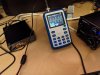
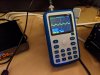
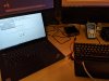
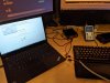
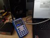
some dummy measurements taken
and 'close' pics showing the detail
tilear A04 (good) = 31.9Vrms with the above settings
new A04 (bad) = 6.82Vrms with the identical settings!!!
the new A04 (bad) had to have the E30 attenuation set to -5.5dB to match ~31.2Vrms, 14.5dB difference!!!!
this is my second unit, so unless i'm getting really unlucky, @AIYIMA changed something. can you provide any response to this massive discrepancy in power output?
EDIT: minor additional detail, looks like the bad one is the rev 3.1 board, whereas the 'good' one is the rev 2.1
some dummy measurements taken
- REW signal generator for 80hz @ -10dBFS
- E30 set to -20dB
- Right channel observed directly to scope, no load (can provide with a speaker load if needed)
- Volume knob on both units set to max, 14AWG ofc wire for testing
and 'close' pics showing the detail
tilear A04 (good) = 31.9Vrms with the above settings
new A04 (bad) = 6.82Vrms with the identical settings!!!
the new A04 (bad) had to have the E30 attenuation set to -5.5dB to match ~31.2Vrms, 14.5dB difference!!!!
this is my second unit, so unless i'm getting really unlucky, @AIYIMA changed something. can you provide any response to this massive discrepancy in power output?
EDIT: minor additional detail, looks like the bad one is the rev 3.1 board, whereas the 'good' one is the rev 2.1
Attachments
Last edited:
somebodyelse
Major Contributor
- Joined
- Dec 5, 2018
- Messages
- 3,754
- Likes
- 3,053
It probably depends how you define 'rated power' - the output power vs. supply voltage charts in the datasheet are for 1% and 10% THD+N while lower distortion levels are usually used for hifi amps, and amirm uses the knee which is lower still. It depends how long you want to sustain it for too - according to pma's tests continuous output is thermally limited due to the relatively poor heatsinking. Within those limits output power and efficiency should pretty much match the datasheet performance for the BTL configuration, but you'll probably have to do a bit of interpolation as the charts there don't match your conditions exactly. Efficiency improves with increased power output, but not massively once you're that far up the curve.Is it possible to predict what rated power an Aiyima A07 will have with X voltage and X amperage power supply?
I’m trying to do my setup in a way so the DAC clips insteads of the amplifier.
would the 85% efficiency (61W at 8 ohm with 48V 3A PSU) measured by amir differ significantly when only amperage is increased?
is it fair to assume a 220W 48V would produce an amplifier with 90W rated power at 8 ohm?
I see no issue as long as the DAC can drive the amp into full power, you just need to increase the DAC's output to drive it to clipping levels.following up
some dummy measurements taken
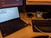
i've provided 'far' pics showing the test setup
- REW signal generator for 80hz @ -10dBFS
- E30 set to -20dB
- Right channel observed directly to scope, no load (can provide with a speaker load if needed)
- Volume knob on both units set to max, 14AWG ofc wire for testing
and 'close' pics showing the detail
tilear A04 (good) = 31.9Vrms with the above settings
new A04 (bad) = 6.82Vrms with the identical settings!!!
the new A04 (bad) had to have the E30 attenuation set to -5.5dB to match ~31.2Vrms, 14.5dB difference!!!!
this is my second unit, so unless i'm getting really unlucky, @AIYIMA changed something. can you provide any response to this massive discrepancy in power output?
It means the two module can produce the same power output, you just need to drive the other one with a higher input signal.
Saw your post in other forum. Looks like the lower gain module has PFFB design on it since one resistor on input has 2.7K resistor (for input summing junction), and the output stage has a larger zobel network. (not sure if there really is PFFB)
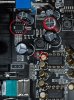
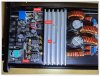
Can you check what IC is used in the attached pic? Encircled in Red.
Also can you check if opamp pin 4 is connected to ground? If it is, then aiyima is using single supply for the opamps., if it's negative voltage relative to ground, then the opamp is using split supply. (just curious)
Regards,
Lester
Attachments
Last edited:
I see no issue as long as the DAC can drive the amp into full power, you just need to increase the DAC's output to drive it to clipping levels.
It means the two module can produce the same power output, you just need to drive the other one with a higher input signal.
thanks for jumping in!
both of my DACs provide 2Vrms, that is on the upper end of most if not all DACs, well over most AVRs. not sure why they would have changed the design to ensure no one is getting full power from the typical sources
Saw your post in other forum. Looks like the lower gain module has PFFB design on it since one resistor on input has 2.7K resistor (for input summing junction), and the output stage has a larger zobel network. (not sure if there really is PFFB)
Can you check what IC is used in the attached pic? Encircled in Red.
the IC is blank, i see no markings at all
Also can you check if opamp pin 4 is connected to ground? If it is, then aiyima is using single supply for the opamps., if it's negative voltage relative to ground, then the opamp is using split supply. (just curious)
yes, pin 4 is grounded
I've attached the PCB posted on the other forum as well
Attachments
The no marking IC might be an opamp for preamp stage, since if there's no preamp, you need more than 2Vrms to drive the output into clipping (when PFFB is enabled).
Gain of TPA3251 non-PFFB BTL is 26dB (x20), if it amplifies the input more, then there's definitely a preamp stage. (datasheet says 20dB per SE output, if it is configured as BTL, then the output doubles so for BTL it's 26dB)
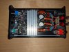
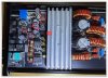
Also, TPA3251 runs hotter than TPA3255 so they increased the heatsink this time.
Is there a tick sound on startup?
Gain of TPA3251 non-PFFB BTL is 26dB (x20), if it amplifies the input more, then there's definitely a preamp stage. (datasheet says 20dB per SE output, if it is configured as BTL, then the output doubles so for BTL it's 26dB)
Also, TPA3251 runs hotter than TPA3255 so they increased the heatsink this time.
Is there a tick sound on startup?
Last edited:
The no marking IC might be an opamp for preamp stage, since if there's no preamp, you need more than 2Vrms to drive the output into clipping (when PFFB is enabled).
Gain of TPA3251 non-PFFB BTL is 26dB (x20), if it amplifies the input more, then there's definitely a preamp stage. (datasheet says 20dB per SE output, if it is configured as BTL, then the output doubles so for BTL it's 26dB)
Also, TPA3251 runs hotter than TPA3255 so they increased the heatsink this time.
Is there a tick sound on startup?
no tick on startup
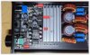
some additional differences noted between cap values on the pre-amp stage and some minorly different ICs
on the output stage, the v3.1 look smaller, but i haven't investigated their values yet
edit: the one pic is mislabeled, the one with the 50v row of caps is the v2.1
Attachments
Last edited:
XL7015 switching regulator is used for converting high DC voltage to around 15VDC. Then LM7812 is used as a post regulator + 10uH inductor for additional HF filtering. (22uH on V2.1). The AMS1117 regulator IC is used for generating 3.3V.
Looks like some minor batch differences, sometimes parts go out of stock so it's normal if they replace them.
Since it is using single supply for the buffer opamps, those 16V 10uF beside the opamps are input signal coupling caps that blocks DC. DC bias is 6V (1/2 opamp supply) so changing from 50V to 16V 10uF is ok.
Input coupling caps have a huge impact on sound, they have changed all input caps to gold/yellow so the 2 modules will sound different. They also changed the output filter caps to smaller, inferior ones (red caps beside the coils) probably to save cost for adding zobel caps in the output area (blue caps)
Wonder if they changed the IC to TPA3255 on the new module. TPA3255 and TPA3251 do not sound the same.
Last edited:
XL7015 switching regulator is used for converting high DC voltage to around 15VDC. Then LM7812 is used as a post regulator + 10uH inductor for additional HF filtering. (22uH on V2.1). The AMS1117 regulator IC is used for generating 3.3V.
Looks like some minor batch differences, sometimes parts go out of stock so it's normal if they replace them.
Since it is using single supply for the buffer opamps, those 16V 10uF beside the opamps are input signal coupling caps that blocks DC. DC bias is 6V (1/2 opamp supply) so changing from 50V to 16V 10uF is ok.
Input coupling caps have a huge impact on sound, they have changed all input caps to gold/yellow so the 2 modules will sound different. They also changed the output filter caps to smaller, inferior ones (red caps beside the coils) probably to save cost for adding zobel caps in the output area (blue caps)
Wonder if they changed the IC to TPA3255 on the new module. TPA3255 and TPA3251 do not sound the same.
dude, give me everything in your brain please
")
thanks for all your responses
This is aiyima's explanation
Recently, we also found that after adding the feedback circuit, the power has been reduced. After re-adjusting our project, the input voltage has been re-adjusted to meet the previous requirements for power recovery and the feedback circuit has also been added. The sound obtained now will sound better under low-power speakers. Does not affect the use of high power
To increase the level of the input signal, you can also reach the previous value.
so not all dissimilar to yours @jlesterp in that, the power output hasn't been hindered and you need a higher input to get there
however, a) how was anyone suppose to know this, b) again, most DAC's commercially available are putting out 1.4-2Vrms, how is anyone making that higher? c) why now do we have to buy more equipment (wouldnt even know what to buy) to power an amp that at one point, was working perfectly fine with standard DACs?
i literally have 93db efficient speakers that i hooked this up to (DIYSG Volt6). At 6ft, i cannot calibrate to reference volume with a 2Vrms DAC without BOOSTING the digital signal (which would potentially cause clipping or hitting cLimiter in windows with EAPO)
EDIT: so some quick measurements, i have (2) 4.5ohm zister 20w resistors that i ran in series for a 9ohm load. on the rev 3.1, with 2Vrms (0dB on the E30 DAC, -3dBFS@80hz from REW) i'm getting 12.6Vrms output
on the rev 2.1 board, same setup, i'm getting about 21.4Vrms before i start to clip. note the volume knob is about 60% when this happens. if i push any higher than about 24-25Vrms, i hit some sort of limiter and it shuts down
on the rev 2.1 board, i maxed the volume on the amp, put E30 to -25dB, and pushed the volume up until i hit clipping around 21.4V which occurred at -10.5dB which measures 0.608Vrms of line output
since i have no way to get greater than 2Vrms of line output, i cannot get the required line it to max the rev 3.1
so it appears that in order to get max output:
rev 2.1 = 0.608V line input
rev 3.1 = unknown, >2V however
Last edited:
Weird, the A04 and A07 have a non-replaceable opamp preamp before the socketed opamp buffers. Yet when they have implemented PFFB on A04 they didn't use the preamp to increase the input sensitivity. Looks like they're aiming for ASR SINAD score too lol. 12Vrms out of 2Vrms input is very very low. (x6 gain in SE mode) TPA325X can only accept 7V rail to rail swing on each input (2.5Vrms max) otherwise it will get overloaded. Means you can only get 15Vrms clean output with x6 gain even if you enter large input signal.dude, give me everything in your brain please
thanks for all your responses
This is aiyima's explanation
so not all dissimilar to yours @jlesterp in that, the power output hasn't been hindered and you need a higher input to get there
however, a) how was anyone suppose to know this, b) again, most DAC's commercially available are putting out 1.4-2Vrms, how is anyone making that higher? c) why now do we have to buy more equipment (wouldnt even know what to buy) to power an amp that at one point, was working perfectly fine with standard DACs?
i literally have 93db efficient speakers that i hooked this up to (DIYSG Volt6). At 6ft, i cannot calibrate to reference volume with a 2Vrms DAC without BOOSTING the digital signal (which would potentially cause clipping or hitting cLimiter in windows with EAPO)
EDIT: so some quick measurements, i have (2) 4.5ohm zister 20w resistors that i ran in series for a 9ohm load. on the rev 3.1, with 2Vrms (0dB on the E30 DAC, -3dBFS@80hz from REW) i'm getting 12.6Vrms output
on the rev 2.1 board, same setup, i'm getting about 21.4Vrms before i start to clip. note the volume knob is about 60% when this happens. if i push any higher than about 24-25Vrms, i hit some sort of limiter and it shuts down
on the rev 2.1 board, i maxed the volume on the amp, put E30 to -25dB, and pushed the volume up until i hit clipping around 21.4V which occurred at -10.5dB which measures 0.608Vrms of line output
since i have no way to get greater than 2Vrms of line output, i cannot get the required line it to max the rev 3.1
so it appears that in order to get max output:
rev 2.1 = 0.608V line input
rev 3.1 = unknown, >2V however
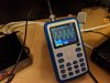
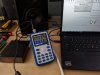
Hmm I think it is a failed configuration. Can you confirm if you can only get 12Vrms out when input is 2Vrms? If you don't have a true RMS multimeter, you can set the signal to 120Hz to 480Hz so that your multimeter can check the rms output correctly.
Weird, the A04 and A07 have a non-replaceable opamp preamp before the socketed opamp buffers. Yet when they have implemented PFFB on A04 they didn't use the preamp to increase the input sensitivity. Looks like they're aiming for ASR SINAD score too lol. 12Vrms out of 2Vrms input is very very low. (x6 gain in SE mode) TPA325X can only accept 7V rail to rail swing on each input (2.5Vrms max) otherwise it will get overloaded. Means you can only get 15Vrms clean output with x6 gain even if you enter large input signal.
Hmm I think it is a failed configuration. Can you confirm if you can only get 12Vrms out when input is 2Vrms? If you don't have a true RMS multimeter, you can set the signal to 120Hz to 480Hz so that your multimeter can check the rms output correctly.
attached are two shots on the scope, the E30 with 2Vrms output, and 12.9Vrms of A04 rev 3.1 output when being fed that signal @80hz
and agreed, this is not great. if these calculators are accurate:
rev 3.1 getting 40W@4ohm and 19W@8ohm (12.8Vrms)
vs
rev 2.1 getting 110W@4ohm and 55@8ohm (21Vrms)
aiyima is PMing me about removing some resistors to increase sensitivity, perhaps you can help decipher
and
If two removed resistors are replaced in this position, the sensitivity will increase again by 1.8 times
so do i do the top one (step A), the bottom one (step B), both?
"If two removed resistors are replaced in this position" - what does this mean, does that mean if i take the resistors of the ones mentioned in step A and move them to this position mentioned in step B?
just unclear what the exact steps are
Attachments
AnalogSteph
Major Contributor
Sure sounds like it. Check whether there is anything installed in this position right now."If two removed resistors are replaced in this position" - what does this mean, does that mean if i take the resistors of the ones mentioned in step A and move them to this position mentioned in step B?
If step A gets you a doubled input sensitivity already, chances are you may not have to do anything more. 12.8 V x 2 = 25.6 V > 21 V, so you should be able to drive the amp into clipping from 2 Vrms.
is it possible to set the input sensitivity of the A07 in a similar way to 1.0V or 2.0V and retire the volume knob?
I don't use my volume knob at all (volume control upstream) and right now i'm using tea leaf reading to decide on which position on the dial is best for me.
my Dac's max output is 1 Vrms and my power supply is 48V 4.6A.
I don't use my volume knob at all (volume control upstream) and right now i'm using tea leaf reading to decide on which position on the dial is best for me.
my Dac's max output is 1 Vrms and my power supply is 48V 4.6A.
I deleted my post since I wasn't able to read the Step B part. Looks like Step A is messing/disabling the PFFB and Step B is changing feedback resistors to increase gain. Agree that you don't need step B.Sure sounds like it. Check whether there is anything installed in this position right now.
If step A gets you a doubled input sensitivity already, chances are you may not have to do anything more. 12.8 V x 2 = 25.6 V > 21 V, so you should be able to drive the amp into clipping from 2 Vrms.
Similar threads
- Replies
- 3
- Views
- 998
- Replies
- 16
- Views
- 2K
- Replies
- 499
- Views
- 84K