• WANTED: Happy members who like to discuss audio and other topics related to our interest. Desire to learn and share knowledge of science required. There are many reviews of audio hardware and expert members to help answer your questions. Click here to have your audio equipment measured for free!

What Kind of Crossover is This?

watchnerd

Grand Contributor
Joined
Dec 8, 2016
Messages
12,449
Likes
10,414
Location
Seattle Area, USA
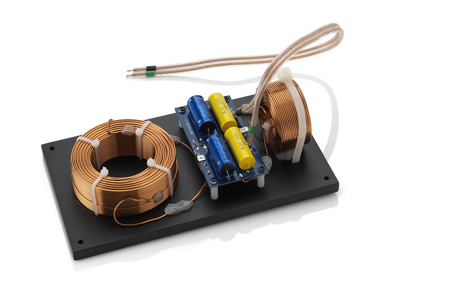
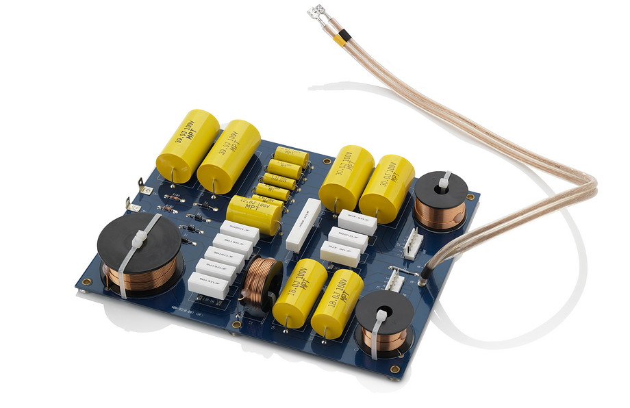
I'm looking at pictures of the stock (first) and DIY-modified (second) crossover for an ATC SCM19 (version 1, I think).

crosover.jpg


xover21.jpg


I see 2 inductors and 2 capacitors per board, which leads me to think 2nd order.

But there is another extra cap that does I don't know what.

And some mysterious white blocks (resistors?) on the stock board, and green tubes and pink tubes (other resistors?) on the DIY board.

Can any of you analog EE types reverse engineer these circuits?
 

DonH56

Master Contributor
Technical Expert
Forum Donor
Joined
Mar 15, 2016
Messages
7,878
Likes
16,657
Location
Monument, CO
The white, green, and pink things are power resistors.

Hard to reverse engineer without being able to see all the wires (hidden on the PCB at top, and some are covered by the inductor foil on the bottom picture). Looking at the bottom picture, best I can tell with a quick look, it looks like the input is the YEL wire on the lower right, and the black is ground. There is a series-L then shunt C with another series-RC shunt to the red wire top left that goes to the woofer. The tweeter goes to a series C then a shunt L to ground, then resistor pad to the tweeter. It is not uncommon to have to pad (attenuate, reduce) the signal to the tweeter to get the output response smooth.

My picture is probably not quite correct or complete but looks reasonable for the pictures provided.

HTH - Don

upload_2017-9-30_9-27-18.png
 
OP
watchnerd

watchnerd

Grand Contributor
Joined
Dec 8, 2016
Messages
12,449
Likes
10,414
Location
Seattle Area, USA
The white, green, and pink things are power resistors.

Hard to reverse engineer without being able to see all the wires (hidden on the PCB at top, and some are covered by the inductor foil on the bottom picture). Looking at the bottom picture, best I can tell with a quick look, it looks like the input is the YEL wire on the lower right, and the black is ground. There is a series-L then shunt C with another series-RC shunt to the red wire top left that goes to the woofer. The tweeter goes to a series C then a shunt L to ground, then resistor pad to the tweeter. It is not uncommon to have to pad (attenuate, reduce) the signal to the tweeter to get the output response smooth.

My picture is probably not quite correct or complete but looks reasonable for the pictures provided.

HTH - Don

View attachment 8875

Is that a Zobel network across the woofer?
 

DonH56

Master Contributor
Technical Expert
Forum Donor
Joined
Mar 15, 2016
Messages
7,878
Likes
16,657
Location
Monument, CO
Yes, to help compensate for the woofer's large inductance. Similar circuits are used extensively for matching devices in the RF world as well as for snubbing the voltage spike generated when switching a relay/solenoid coil on and off. I rarely use "Zobel" for this circuit and usually call it a snubber circuit.

Zobel was a Bell Labs guy who developed a class of filter networks based on image theory IIRC. Long before my time, back in the 1920's or 1930's, I think. A Zobel network to me is a bridged-T network, a very clever matching network often used in HF circuits today to "tune out" the capacitance of the big ESD diodes at the input and output pads of HF chips.

Edit -- Found a reference: https://en.wikipedia.org/wiki/Zobel_network and specifically https://en.wikipedia.org/wiki/Zobel_network#Bridged_T_implementation
 
OP
watchnerd

watchnerd

Grand Contributor
Joined
Dec 8, 2016
Messages
12,449
Likes
10,414
Location
Seattle Area, USA
Yes, to help compensate for the woofer's large inductance.

I know the answer to this question is probably "it depends", but is such compensation necessary or just a precaution? If the driving amp has low output impedance and high damping factor, is inductance such an issue?
 

Blumlein 88

Grand Contributor
Forum Donor
Joined
Feb 23, 2016
Messages
20,690
Likes
37,414
The zobel will help the crossover work at the desired frequencies and slopes. They aren't so much for the amp as to make the crossover work closer to textbook fashion.
 
OP
watchnerd

watchnerd

Grand Contributor
Joined
Dec 8, 2016
Messages
12,449
Likes
10,414
Location
Seattle Area, USA
The zobel will help the crossover work at the desired frequencies and slopes. They aren't so much for the amp as to make the crossover work closer to textbook fashion.

Ah, thank you!

So if one wanted to rip out the passive crossover and go externally active DSP crossover / amp, this can be ignored, right?
 

Blumlein 88

Grand Contributor
Forum Donor
Joined
Feb 23, 2016
Messages
20,690
Likes
37,414
Ah, thank you!

So if one wanted to rip out the passive crossover and go externally active DSP crossover / amp, this can be ignored, right?

Yes, unless you were using an amp with a high output impedance, then a Zobel would change what the amps sees, but not effect the output of the driver. So it would be useless with DSP and amps directly connected to the driver.
 

DonH56

Master Contributor
Technical Expert
Forum Donor
Joined
Mar 15, 2016
Messages
7,878
Likes
16,657
Location
Monument, CO
I know the answer to this question is probably "it depends", but is such compensation necessary or just a precaution? If the driving amp has low output impedance and high damping factor, is inductance such an issue?

Answered above by @Blumlein 88 . It acts as a snubber, but also provides impedance-matching to the crossover to present a more constant load to the crossover and thus better control the transfer function. Net result is smoother frequency response.

If the amplifier is directly attached you probably do not need the Zobel but it can make it easier on the amplifier. With a SS amplifier it probably doesn't help much unless the amplifier has stability issues or high'ish output impedance; it may benefit a tube amplifier more due to its higher output impedance. In the past I would sometimes retain the RC in an active design to help reduce charge kick-back from the driver and help the amplifier's stability (sometimes the charge kick can look like wideband impulses).

Note that passive crossovers tend to buffer and reduce impedance variation from drivers and so a passive speaker may actually present an easier load than an active design with amplifiers connected directly to the drivers.
 
OP
watchnerd

watchnerd

Grand Contributor
Joined
Dec 8, 2016
Messages
12,449
Likes
10,414
Location
Seattle Area, USA
Answered above by @Blumlein 88 . It acts as a snubber, but also provides impedance-matching to the crossover to present a more constant load to the crossover and thus better control the transfer function. Net result is smoother frequency response.

If the amplifier is directly attached you probably do not need the Zobel but it can make it easier on the amplifier. With a SS amplifier it probably doesn't help much unless the amplifier has stability issues or high'ish output impedance; it may benefit a tube amplifier more due to its higher output impedance. In the past I would sometimes retain the RC in an active design to help reduce charge kick-back from the driver and help the amplifier's stability (sometimes the charge kick can look like wideband impulses).

Note that passive crossovers tend to buffer and reduce impedance variation from drivers and so a passive speaker may actually present an easier load than an active design with amplifiers connected directly to the drivers.

The amp in question, in my case, is a Devialet 400 Pro, dual mono, with an output impedance of .001 ohm.
 
OP
watchnerd

watchnerd

Grand Contributor
Joined
Dec 8, 2016
Messages
12,449
Likes
10,414
Location
Seattle Area, USA
An interesting contrast to the relatively simple ATC SCM19 crossover is the one below for the JBL 4367. Interestingly, both are two-ways, but the 4367 is so complex / sophisticated it's on two boards, has battery-coupled capacitors, and clearly has 'a lot going on':

JBL_4367-17.jpg

JBL_4367-16.jpg
 
OP
watchnerd

watchnerd

Grand Contributor
Joined
Dec 8, 2016
Messages
12,449
Likes
10,414
Location
Seattle Area, USA
As already said, yes. My dsp xo speakers are directly connected to the amps with no adverse effects.

What's your recommendation for the best way to measure driver sensitivity to set the levels correctly?
 

March Audio

Master Contributor
Audio Company
Joined
Mar 1, 2016
Messages
6,378
Likes
9,319
Location
Albany Western Australia
I use an Earthworks M23 measurement mic, but the usb umik mic from minidsp is also works well. Used with REW and Acourate software. Also remember that in room driver measurements are problematic at low frequencies. A good idea to make them in an open space such as your garden.

Excuse me if youv already know this, but remember you will probably need further correction and not just the crossover filtering. Passive xos often have frequency response corrections built in to them, not least of which the baffle step correction.

Can you remind me what you are using to do the xo filtering and its capabilities?
 
OP
watchnerd

watchnerd

Grand Contributor
Joined
Dec 8, 2016
Messages
12,449
Likes
10,414
Location
Seattle Area, USA
I use an Earthworks M23 measurement mic, but the usb umik mic from minidsp is also works well. Used with REW and Acourate software. Also remember that in room driver measurements are problematic at low frequencies. A good idea to make them in an open space such as your garden.

Excuse me if youv already know this, but remember you will probably need further correction and not just the crossover filtering. Passive xos often have frequency response corrections built in to them, not least of which the baffle step correction.

Can you remind me what you are using to do the xo filtering and its capabilities?

I have a umik that came with my miniDSP. I assume you're measuring with the drivers mounted in the box/baffle?

What test signal are you using?
 
OP
watchnerd

watchnerd

Grand Contributor
Joined
Dec 8, 2016
Messages
12,449
Likes
10,414
Location
Seattle Area, USA
The white, green, and pink things are power resistors.

Hard to reverse engineer without being able to see all the wires (hidden on the PCB at top, and some are covered by the inductor foil on the bottom picture). Looking at the bottom picture, best I can tell with a quick look, it looks like the input is the YEL wire on the lower right, and the black is ground. There is a series-L then shunt C with another series-RC shunt to the red wire top left that goes to the woofer. The tweeter goes to a series C then a shunt L to ground, then resistor pad to the tweeter. It is not uncommon to have to pad (attenuate, reduce) the signal to the tweeter to get the output response smooth.

My picture is probably not quite correct or complete but looks reasonable for the pictures provided.

HTH - Don

View attachment 8875

Below is the schematic for the older, closely related SCM20 (same mid/woofer, but with a Vifa tweeter, instead). I think your photo-derived schematic is pretty close!

crossover.gif
 
OP
watchnerd

watchnerd

Grand Contributor
Joined
Dec 8, 2016
Messages
12,449
Likes
10,414
Location
Seattle Area, USA
Its swept sine. I take it you havent played with REW? Its free. Yes the speakers are in the box.

I haven't used REW. I've used the horrible software that miniDSP provides to configure the box, Roon convolution filters, Pro Tools, and Matlab.
 
OP
watchnerd

watchnerd

Grand Contributor
Joined
Dec 8, 2016
Messages
12,449
Likes
10,414
Location
Seattle Area, USA

March Audio

Master Contributor
Audio Company
Joined
Mar 1, 2016
Messages
6,378
Likes
9,319
Location
Albany Western Australia
I haven't used REW. I've used the horrible software that miniDSP provides to configure the box, Roon convolution filters, Pro Tools, and Matlab.

ReW is great. Download it and start playing. The umik works directly with it. Make sure you load the calibration file that comes with the mic.

I have played with a lot of diffetent methodolgies before settling on a solution. Including minidsp, but Acourate has been by far the best.
 
Top Bottom