• WANTED: Happy members who like to discuss audio and other topics related to our interest. Desire to learn and share knowledge of science required. There are many reviews of audio hardware and expert members to help answer your questions. Click here to have your audio equipment measured for free!

What is a typical audio amplifier input impedance?

DonH56

Master Contributor
Technical Expert
Forum Donor
Joined
Mar 15, 2016
Messages
7,878
Likes
16,657
Location
Monument, CO
After skimming the passive volume control review, I was starting to run some numbers with the idea of a simple note and maybe sim circuit or spreadsheet showing how a passive volume control can affect frequency response (as well as volume, natch). But, I realized that I have a decent idea of the input resistance for various amplifiers, but not a good idea of the input capacitance (I assume input inductance is negligible). I have some old, old numbers I have used that show around 100 pF but I don't trust that as a general reference. Most datasheets don't seem to spec anything or only Rin, and if they have Cin it is usually only for the phono input of an integrated amp.

Sooo, what have you amplifier designers/reviewers measured for typical amplifiers' line inputs? Any data? I confess it is not something I think about much , and a quick search revealed a lot of (make that "some") numbers for Rin but virtually none for Cin.

Curious, thanks - Don
 
Last edited:

pma

Major Contributor
Joined
Feb 23, 2019
Messages
4,602
Likes
10,768
Location
Prague
Input RC filters of power amplifiers affect the input impedance as a function of frequency of these instruments. I have seen values spread like

R = {100 ohm; 10 kohm}
C = {100 pF; 2nF}

so it is really difficult to give any "universal" answer and universal number.
An active preamp with output impedance of 50 - 100 ohm will have no issues, but consider 10k passive pot with up to 2.5k output resistance and it is a different story.
 
OP
DonH56

DonH56

Master Contributor
Technical Expert
Forum Donor
Joined
Mar 15, 2016
Messages
7,878
Likes
16,657
Location
Monument, CO
Input RC filters of power amplifiers affect the input impedance as a function of frequency of these instruments. I have seen values spread like

R = {100 ohm; 10 kohm}
C = {100 pF; 2nF}

so it is really difficult to give any "universal" answer and universal number.
An active preamp with output impedance of 50 - 100 ohm will have no issues, but consider 10k passive pot with up to 2.5k output resistance and it is a different story.
Thanks, and yes it is the passive "preamp" case I had in mind to analyze. I have not seen a power amp with 100-ohm Rin; most seem to be in the 10k to 100k range, and with 10k ohms then Cin ~ 100 pF yields a simple corner of around 159 kHz, ignoring the source impedance ("infinite"). Usually they want to suppress the AM band up around 500 kHz (in the USA) so having a couple octaves' roll-off was the old rule-of-thumb with the input stage, preamp's output, and cable shielding providing the rest of the rejection. Except for a few "ultrawideband" amplifiers I am used to measuring around 100 kHz small-signal bandwidth but am not sure how much of that is the input filter.

Seems like my old 100 pF/10k-ohm might not be far off to use for a simple analysis to show how much a passive pot can affect things... With a 10k pot, which Amir measured, 100k-ohm amplifier Rin will be swamped by the pot.

Thanks!
 
OP
DonH56

DonH56

Master Contributor
Technical Expert
Forum Donor
Joined
Mar 15, 2016
Messages
7,878
Likes
16,657
Location
Monument, CO
OK, I had some time to do a little more research. Without listing all the details, after some mind-numbing looking at schematics and references I have on hand, 100 pF after a small (10~100 ohm) series input resistor seems pretty common. A couple of amps I have schematics for used that value, along with several of the circuits in Douglas Self's amplifier design books. A similar range of values was in a couple of other texts (like Bob Cordell's power amp book) so it seems reasonable. There were some other designs using up to 300~500+ pF for more aggressive roll-off/EMI rejection. And a few incorporated an ultrasonic filter using 2~4 nF capacitors (and larger series resistors), the largest I saw in my (relatively) quick look. I did not consider Miller input capacitance; most (but not all) circuits I saw are designed to mitigate that effect.

The plus is I found several of my old audio reference books, set aside when my career took a different path and/or when Family, Life, and Work consumed all free time and I set aside any hobbies. I did find several copies of Self's books, all three revisions of Toole's book, several versions of Everest's Handbook, etc. Along with several duplicates of other reference books bought (and forgotten) over the years...
 

Lambda

Major Contributor
Joined
Mar 22, 2020
Messages
1,791
Likes
1,525
From what i have seen:
Input series resistance is in the rang from 0-1K
Input capacitor is around 200pF-2nF range
Bias resistance to ground is around 2-100K
 

MakeMineVinyl

Major Contributor
Joined
Jun 5, 2020
Messages
3,558
Likes
5,873
Location
Santa Fe, NM
Don't have schematics in front of me but I'll check Monday.
 

pma

Major Contributor
Joined
Feb 23, 2019
Messages
4,602
Likes
10,768
Location
Prague
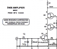
Just a few ...
 

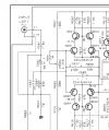
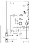
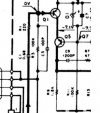
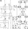
Attachments

  • 1090in.png
    1090in.png
    40.3 KB · Views: 153
  • rmbin.png
    rmbin.png
    12.9 KB · Views: 160
  • 5010in.png
    5010in.png
    88.7 KB · Views: 138
  • HCA1000in.png
    HCA1000in.png
    23.5 KB · Views: 132
  • D400in.png
    D400in.png
    65.1 KB · Views: 149
  • A21in.png
    A21in.png
    36.1 KB · Views: 164

LTig

Master Contributor
Forum Donor
Joined
Feb 27, 2019
Messages
5,808
Likes
9,515
Location
Europe
Looking at specs there is always the difference between stated impedance and measured impedance. @John Atkinson always measures input impedance of power amps at Stereophile and some measure as specced, some don't, some differ at high or low frequencies only. I haven't recognized a pattern so far.
 

wwenze

Major Contributor
Joined
May 22, 2018
Messages
1,310
Likes
1,871
I assume a worst case of 1kohm into ground and work with that.

Remember that the input impedance is not exactly easy to figure out since the active devices also have a non-zero conductance, in particular those with bipolar input stages. LM4562 for example has a differential input impedance of 30kohm, while OPA604 is 10^12.

Why 1kohm tho? Because that's around what I remember was the input impedance for a few class D amps, and they have a varying impedance vs frequency so you needed a pretty low source impedance to prevent your volume control from becoming a tone control.
 

Blumlein 88

Grand Contributor
Forum Donor
Joined
Feb 23, 2016
Messages
20,690
Likes
37,415
I assume a worst case of 1kohm into ground and work with that.

Remember that the input impedance is not exactly easy to figure out since the active devices also have a non-zero conductance, in particular those with bipolar input stages. LM4562 for example has a differential input impedance of 30kohm, while OPA604 is 10^12.

Why 1kohm tho? Because that's around what I remember was the input impedance for a few class D amps, and they have a varying impedance vs frequency so you needed a pretty low source impedance to prevent your volume control from becoming a tone control.
1 k ohm is too low. Very few amps have an input impedance that low. I don't recall seeing any that low, but maybe there are some. 10 k ohm isn't uncommon nor are values between there and up to 100 k ohms.
 

Sokel

Master Contributor
Joined
Sep 8, 2021
Messages
6,019
Likes
6,022
1200as2.PNG

Ice Edge 1200as2

300a2.PNG

Ice Edge 300a2
 

pma

Major Contributor
Joined
Feb 23, 2019
Messages
4,602
Likes
10,768
Location
Prague
As the point here is the complex input impedance, Rs - R//C, we are also interested in input capacitance and possibly also in a series resistor Rs of the input anti RFI filter. The mere 38k number is not enough, as it says nothing about impedance as a function of frequency.
 

Sokel

Master Contributor
Joined
Sep 8, 2021
Messages
6,019
Likes
6,022
As the point here is the complex input impedance, Rs - R//C, we are also interested in input capacitance and possibly also in a series resistor Rs of the input anti RFI filter. The mere 38k number is not enough, as it says nothing about impedance as a function of frequency.
That kind of info must be available to you as a technician through their intranet.I cannot get it.
 

MakeMineVinyl

Major Contributor
Joined
Jun 5, 2020
Messages
3,558
Likes
5,873
Location
Santa Fe, NM
Balanced 2 pole input filter - 100R/100pF, 499R/220pF on each side shunted by 220pF/49.9k.
 
OP
DonH56

DonH56

Master Contributor
Technical Expert
Forum Donor
Joined
Mar 15, 2016
Messages
7,878
Likes
16,657
Location
Monument, CO
Good info, thanks all!

I did my analysis using the 100 pF I found in schematics and books I had at hand, probably good enough for now, but this provides info to tweak the sims and for future use. I may run the sim again with a higher value to see if it creeps into the audio band. (Pause: with the passive control at 50%, worst-case for bandwidth, and 400 pF amp Cin, the SS circuit is -3 dB at 200 kHz and the tube circuit at 20 kHz, both a little lower than before but not a huge change.)

The only amp with 1k-ohm input I recall was one of the unbuffered class-D modules. IIRC the assumption was an input buffer would be provided in a complete amplifier design. 10k ohms and up is pretty standard for SS, with tubes 100k or so, at least IME.

Edit: I added another plot to my passive attenuator thread, increasing the amp's Cin to 400 pF, which seems above most all but the ones with a heavy-duty ultrasonic filter using a few nF. I neglected the input R since the passive volume control's resistance swamps it for most of the control's range.
 
Last edited:

Lambda

Major Contributor
Joined
Mar 22, 2020
Messages
1,791
Likes
1,525
OP
DonH56

DonH56

Master Contributor
Technical Expert
Forum Donor
Joined
Mar 15, 2016
Messages
7,878
Likes
16,657
Location
Monument, CO
It's more than just the pot; you have to consider the other elements of the circuit involved, since they affect the overall transfer function. If it was just a one-pole RC I could do that on my hand calculator, no need to sim it. For example, a 10k pot at halfway point is 5k to each side, with the input driven by the preamp and output shunted by the amp's input, plus cable capacitance affects the roll-off. It is unlikely to match the bandwidth given by a 10k/800pF RC filter. I actually wrote out the equations on a piece of paper for my model circuit with the idea of just calculating the -3 dB point, but decided it was too much work (and too large a chance of a simple math error (by me) mucking up the results).

For the attenuator thread, I just focused on frequency response so did not look at thermal (or any other) noise. Again, you'd have to consider the entire circuit and not just the maximum resistance of the pot. I wanted to show folk how the passive attenuator not only limited bandwidth, but changed with the control (volume) setting. I thought about doing a noise sim but decided that was outside the scope of this thread. Ditto things like amp input bias current causing distortion, adding shot noise, and so forth. Easier for me to focus on just one thing at a time, at least in the attenuator thread.

This might be a good thread to bring up some of those other items, however, where we have an audience that can take it beyond my simple stuff. There is already a lot wider variation in input filters than I had expected (though should have). Perhaps the discussion will lead to other articles (not necessarily by me) that dig a little deeper.
 
Last edited:
Top Bottom