Note that nearly every loudspeaker has an inductive rise in the top octave, so not only is the load not 8 ohms, it's not resistive. Not that this matters at minuscule fractions of a wavelength...

-
WANTED: Happy members who like to discuss audio and other topics related to our interest. Desire to learn and share knowledge of science required. There are many reviews of audio hardware and expert members to help answer your questions. Click here to have your audio equipment measured for free!
You are using an out of date browser. It may not display this or other websites correctly.
You should upgrade or use an alternative browser.
You should upgrade or use an alternative browser.
Townsend Isolda cable
- Thread starter Purité Audio
- Start date
- Status
- Not open for further replies.
solderdude
Grand Contributor
Solderdude. My suggestion is to use unconditionally stable amplifiers (99% of all amps).
See another simulation TymsCables.
That would be my suggestion too, however, not all amp manufacturers practice this as well. In those cases a high capacitance load combined with a rising impedance is a recipe for disaster where the same disaster may not happen with a lower capacitance cable.
A question could be where the back EMF comes into play ?
I don't see it mentioned anywhere yet I think this is more relevant than an (attenuated) echo from a few meters away ?
Why would an echo manifest itself as a 50kHz roll-off at large lengths ?
One would assume that an echo would be seen as a peak after the initial rise instead of an attenuation at the start of the squarewave.
More similar to that of digital data transmission in a badly terminated transmission line.
The transmission line only works well when the source resistance matches the load and transmission line as far as I have seen.
And this isn't because speakers are one way direction.
It goes in both directions due to back EMF as well.
I don't see this in any of the papers yet is very real.
I have looked at very steep risetime square-waves at the end of a cable with a scope and only saw a gentle roll-off consistent with the cable's inductance and capacitance and behaves the same as it would using a regular capacitor in a very short circuit (a few cm) so that would rule out any echo's.
Maybe I haven't looked hard enough and/or your conclusions may be ?
I believe the Tymscable simulation is wrong.. why ? because a able cannot be simulated by simple R-C-L components and I don't see cable lengths included.
I only see different L, C and R values creating a difference which is logical... otherwise the simulation is poor.
Also use the same sim software and sometimes (actually almost always) found differences with real world components.
It is not possible to simulate PCB traces, connector effects etc. using just 1 L, C and R and propagation delay etc.
Have nulled cables in the past and even with a few meters you really need to have the reference branch have the same length as the cable under test otherwise you start to see small differences due to phase differences above the audible range.
- Joined
- Mar 22, 2019
- Messages
- 129
- Likes
- 30
That amplifier seems to be the Cambridge Audio Topaz AM10. I can't find a measurement of it but the specs say it is down -1 dB between 5 Hz and 50 kHz. That tells me its actual bandwidth is quite bit better than this. So my point remains. Square wave with wide bandwidth is not a proper test unless it is band limited to the audible frequencies.
You are all clutching at straws. Here is a video where the difference between the amplifier end and the speaker end is amplified and played through a speaker. The audio is from the Canon camera which has AGC, so it masks the huge level difference between the between the Isolda and Monster.
The first part of the video is 8/6.7 ohm Isolda and the second part of the video 120 ohm Monster. My wife can hear the difference from the kitchen.
https://drive.google.com/file/d/13LY4M0_CdC9aOW6kfTWZafEfv_MyD08q/view?usp=sharing
Yes, the sound is bad on both, because it is in the factory and it is not really loud, but there is a difference. I did this on the fly! No editing. A better video follows.
Attachments
- Joined
- Mar 22, 2019
- Messages
- 129
- Likes
- 30
Note that nearly every loudspeaker has an inductive rise in the top octave, so not only is the load not 8 ohms, it's not resistive. Not that this matters at minuscule fractions of a wavelength...
We put a Zobel network in the speaker end of Isolda cable to account for this. 0.22uF in series with 10R across the wires in the box.
2 x 1.5uh is in the amplifier end.
This is Hi Fi, not audio.
solderdude
Grand Contributor
Why not send a sample of your cable to Amir and see what he measures compared to generic cables.
I wish I could use my wife to trouble shoot issues... could come in handy.
Seems like I married the wrong one though.")
I wish I could use my wife to trouble shoot issues... could come in handy.
Seems like I married the wrong one though.
solderdude
Grand Contributor
We put a Zobel network in the speaker end of Isolda cable to account for this. 0.22uF in series with 10R across the wires in the box.
2 x 1.5uh is in the amplifier end.
The zobel at the speaker side makes sense.
Would such also be needed for line level interlinks ?
- Joined
- Mar 22, 2019
- Messages
- 129
- Likes
- 30
Why not send a sample of your cable to Amir and see what he measures compared to generic cables.
I wish I could use my wife to trouble shoot issues... could come in handy.
Seems like I married the wrong one though.
My wife had more records than me when I met her (1972)! Lucky or what?
solderdude
Grand Contributor
Not so in my case ... besides we had different tastes in music.
Nah, it is easy picking.You are all clutching at straws.
There is a reason in the entire library of thousands of papers at AES, not one speaks of the matters in your documents.Here is a bit from your second paper:
Far fetched it is. And the simple explanations are wrong. Here is another example in the same paper:
Once again, "very fast rise time pulses" are assumed. I already explained why that is such a faulty assumption. The math, not conjecture, tells us this relationship between bandwidth and rise time:
For you to have very fast rise time, tr needs to be very small. That translates into BW (bandwidth) being very wide. Audio has anything but wide bandwidth. 20 Hz to 20 kHz is nothing compared to gigahertz of bandwidth we use in RF for example. That is why the things you talk about matter tremendous in radio communications, and not at all in audio.
Then there is this:
45 kHz? Where did you get that? Have you done a listening test between a system with band limit of 22 kHz and then 44 kHz? Can you post controlled test results showing that? Or some references to psychoacoustics journals, papers, etc.?
At your and my age, we can't even hear 15 kHz let alone three times as much as 45 kHz. So if you are hearing the difference between your cables, then the effect must by definition be limited to 15 kHz and lower.
Also, the power of the spectrum in music at high frequencies is very low. So any simulations or arguments you make, has to assume levels at high frequencies at very low levels compared to mid frequencies. Ditto for "reflections." Here is a very well recorded random sample in my library from 2L label at 88 kHz sampling:
By the time we get to 20 kHz, response is down 70 dB. By your stated goal of 45 khz, there is nothing. Put this data in your simulation and see what you get.
The zobel at the speaker side makes sense.
Would such also be needed for line level interlinks ?
Or just using normal wire. Not as good for commerce, but technically fine for audio.
From the same paper:

Exactly what instruments have you used to make this statement? My Audio Precision analyzer has a bandwidth of 1 Mhz. It can generate signals up to 200 kHz. It has a dynamic range better than any power amplifier by far. Its frequency response is ruler flat. In every way the analyzer exceeds our hearing sensitivity sometimes by massive (orders of magnitude) more sensitivity.
Exactly what instruments have you used to make this statement? My Audio Precision analyzer has a bandwidth of 1 Mhz. It can generate signals up to 200 kHz. It has a dynamic range better than any power amplifier by far. Its frequency response is ruler flat. In every way the analyzer exceeds our hearing sensitivity sometimes by massive (orders of magnitude) more sensitivity.
- Joined
- Mar 22, 2019
- Messages
- 129
- Likes
- 30
Luckily, most interconnects have Zc between 50 ohms and 100 ohms, which is pretty close to source impedances of 50 to 80 ohms (source), into 10-20K ohms (load), (back matching Deletraz). This is fine and not too bad.The zobel at the speaker side makes sense.
Would such also be needed for line level interlinks ?
However, when compared with speaker (4-8 ohms), driven by grossly miss-matched 100 to 300 ohms speaker cables, the sound is not not so good. It causes the multiple reflections:- Hundreds+ of them, on every musical transient, which add up to noise and distortion all over your music.
Just because first gear is not perfectly matched to maximum torque and HP from 1000 to 5000 RPM, it is not a good idea to take off at the lights in 5th gear!
The art of engineering is to optimise your compromise.
Characteristic impedance is irrelevant for the wavelengths involved. You can’t change physics even if your wallet is involved.
- Joined
- Mar 22, 2019
- Messages
- 129
- Likes
- 30
From the same paper:
View attachment 23983
Exactly what instruments have you used to make this statement? My Audio Precision analyzer has a bandwidth of 1 Mhz. It can generate signals up to 200 kHz. It has a dynamic range better than any power amplifier by far. Its frequency response is ruler flat. In every way the analyzer exceeds our hearing sensitivity sometimes by massive (orders of magnitude) more sensitivity.
Yes, I agree, but please pay attention as to how you use your gorgeous equipment.
I am demonstrating everything on the most basic equipment. Please try the experiment yourself.
Yes, it's basic equipment if I'm trying to connect a VHF transmitter to an antenna. Do you have an experiment relevant to audio?
Do you have listening test results (ears-only) using engineered amplification demonstrating audibility of the stuff you're claiming?
Do you have listening test results (ears-only) using engineered amplification demonstrating audibility of the stuff you're claiming?
solderdude
Grand Contributor
The art of engineering is to optimise your compromise.
In your cable geometry 'evidence' simulation I see you are using a 5MHz squarewave (with almost infinite BW) which produces 2.5MHz ringing and is supposed to be evidence of the poor SQ.
How is that (poor) simulation relevant to audio even when we consider the audible band is 50kHz.
Why would a reflection cause a slower rising edge at the end point of the cable ?
One would think the LCR low pass filter that is created is responsible for this.
Why would an almost immediate reflection (which would be heavily damped by the close to 0 Ohm source) cause the voltage to rise slower at the end point ? They would be in phase as the wavelength is km long in audio frequencies... why would reflections 'cancel' when they would always be in phase ?
I'm still trying to figure out how one Zobel is adequate to flatten the impedance curve of any speaker. Or if the purchasers are supposed to calculate and build custom Zobels. So many questions, so little relevance to audio!
Then we have this:

Spreading the myth that we need impedance matching for audio. We absolutely do not. A power amplifier has impedance very close to zero. Let's assume zero for simplicity. Let's have an 8 ohm speaker. Now, add a speaker wire with 8 ohm resistance/impedance and now you have a voltage divider:
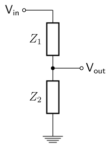
Z1 will be your speaker wire and Z2 will be the speaker. Vin will be the amplifier. If Z1 is 8 ohm as Z2, then it will dissipate half the power the amplifier delivers to the speaker! Same current goes through both resistors so the math dictages power through Z1 is Z1 * I as will Power through Z2= I * Z2.
Raise your hand if you want your speaker wire to throw away half of your power. Good, I don't see any hands raised.
For RF situations or where cables are kilometers long as is with analog telephone we have reflections to worry about so matching impedances are used as you indicate. But for audio, we do not and as such, this is absolutely wrong thing to do. Wire resistance/impedance must be kept to minimum in order to reduce its losses.
In addition to straight losses, speaker impedance varies with frequency. If the wire resistance/impedance is a significant fraction of the speaker impedance, it will server to change its frequency response which again, is a bad thing.
I suggest reading Snow's 1957 Journal of AES paper, Impedance -- Matched or Optimum? Here is the synopsis:


This dog does not hunt. It didn't in 1957, and doesn't today. Simple, basic understanding of electrical systems and transmission stipulates this.
Spreading the myth that we need impedance matching for audio. We absolutely do not. A power amplifier has impedance very close to zero. Let's assume zero for simplicity. Let's have an 8 ohm speaker. Now, add a speaker wire with 8 ohm resistance/impedance and now you have a voltage divider:
Z1 will be your speaker wire and Z2 will be the speaker. Vin will be the amplifier. If Z1 is 8 ohm as Z2, then it will dissipate half the power the amplifier delivers to the speaker! Same current goes through both resistors so the math dictages power through Z1 is Z1 * I as will Power through Z2= I * Z2.
Raise your hand if you want your speaker wire to throw away half of your power. Good, I don't see any hands raised.
For RF situations or where cables are kilometers long as is with analog telephone we have reflections to worry about so matching impedances are used as you indicate. But for audio, we do not and as such, this is absolutely wrong thing to do. Wire resistance/impedance must be kept to minimum in order to reduce its losses.
In addition to straight losses, speaker impedance varies with frequency. If the wire resistance/impedance is a significant fraction of the speaker impedance, it will server to change its frequency response which again, is a bad thing.
I suggest reading Snow's 1957 Journal of AES paper, Impedance -- Matched or Optimum? Here is the synopsis:
This dog does not hunt. It didn't in 1957, and doesn't today. Simple, basic understanding of electrical systems and transmission stipulates this.
- Status
- Not open for further replies.
Similar threads
- Replies
- 30
- Views
- 2K
- Replies
- 14
- Views
- 853