• WANTED: Happy members who like to discuss audio and other topics related to our interest. Desire to learn and share knowledge of science required. There are many reviews of audio hardware and expert members to help answer your questions. Click here to have your audio equipment measured for free!

TotalDAC USB cable/filter - Teardown

Kevbaz

Active Member
Joined
Sep 22, 2021
Messages
225
Likes
366
Location
West Yorkshire England
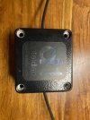
This week I received a TotalDAC USB cable/filter from a friend who was throwing it out. He was happy to let me have it to try out and take apart.
I tested the TotalDAC USB cable/filter with a Chord Mojo (data only), Schiit Fula (data + Power) and a Hidizs S8 (power+Data). I had my eldest son swap between the TotalDAC USB cable/filter and a plain cheap Rino USB cable from amazon. Sometimes he swapped the Rino out and the Rino back in and sometimes swapped in the TotalDAC USB cable/filter. All of this was blind to me. I could hear no difference and couldn't tell which cable was been used each time.

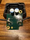
Getting in to the box was a pain due to the epoxy/resin on the screws. Once chipped out, it was easy with bench drill to drill out the screws.
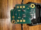
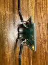
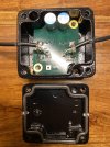
The soldering looks pretty poorly done, with flux everywhere. Also the USB cable was damaged where it must have been crushed by the box.

More details of the USB cable/filter can be found at http://www.totaldac.com/cables-eng.htm cost is 360euros incl VAT in Europe.
dac1.jpeg

dac2.jpeg

dac3.jpeg

dac4.jpeg

dac5.jpeg
 

solderdude

Grand Contributor
Joined
Jul 21, 2018
Messages
16,021
Likes
36,337
Location
The Neitherlands
Looks like an EMC common mode ferrite bead for data.
Looks like the screen/ground has a small resistor + parallel capacitor in series.
The +5V goes past a couple of ceramic, tantalum and electrolytic capacitors for filtering.

A bit like the jitterbug but with more capacitance in the 5V path.

A sharper picture of the bottom of the board may reveal a bit more.

Amir measured it.
 
Last edited:
OP
Kevbaz

Kevbaz

Active Member
Joined
Sep 22, 2021
Messages
225
Likes
366
Location
West Yorkshire England
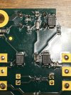
below is a better photo of bottom.

dac6.jpeg

Hopefully this gives better view of the components.
 
OP
Kevbaz

Kevbaz

Active Member
Joined
Sep 22, 2021
Messages
225
Likes
366
Location
West Yorkshire England
Just horrible. Looks like they even hand soldered the SMD parts?
The SMD components do look hand soldered and wonky with excess flux :(
 

solderdude

Grand Contributor
Joined
Jul 21, 2018
Messages
16,021
Likes
36,337
Location
The Neitherlands
below is a better photo of bottom.

View attachment 176282

Hopefully this gives better view of the components.

The black SMD parts are most likely ESD protection diodes or TVS
They looked a bit like tantalum caps but markings suggests semiconductors.
 
Last edited:

voodooless

Grand Contributor
Forum Donor
Joined
Jun 16, 2020
Messages
10,383
Likes
18,317
Location
Netherlands
That’s probably less than € 4 in parts, less than 50 cents for the PCB, and then a few € for the cable and box print and epoxy. This is definitely below € 15,- fully assembled, possibly below € 10,- even.
 

Koeitje

Major Contributor
Joined
Oct 10, 2019
Messages
2,306
Likes
3,964
What a joke.
 

Matias

Master Contributor
Forum Donor
Joined
Jan 1, 2019
Messages
5,072
Likes
10,922
Location
São Paulo, Brazil
@Superdad can you describe what they used here?
 

Spkrdctr

Major Contributor
Joined
Apr 22, 2021
Messages
2,223
Likes
2,944
Ok, I will let the flux issue go as it is not all that important, but hand soldering the SMD devices is wonky. I am amazed at how it all looks like it was a high school science project. The wiring going to the board is horrendous. I mean BAD. It shows that they farmed it out to someone who really had no clue what they were doing, or they did it themselves and still had no clue. I have to say I'm mortified after seeing those pics. Great job Amir!
 

RndmLstner

Member
Joined
Sep 18, 2019
Messages
29
Likes
63
Edit: This item was previously measured and briefly discussed here.

(1) Can we tell from the design/implementation what the technical goal was?
(2) What precisely does the design and implementation achieve?
(3) Does the design/implementation achieve the following at any level: "The filter box embeds also a circuit to better protect your DAC from the possible over-voltages coming from the computer."

I understand this wasn't measured but perhaps one can draw general conclusions by examining the design/implementation.

Thanks. Please understand from a non-technical perspective, there has been discussion regarding its poor implementation but no discussion what the implementation tells us as to integrity of the product/marketing. And for those without technical knowledge, the reveal itself doesn't provide any insight (vs if the box was empty even a non technical person could draw conclusions) which is an important part of ASR for the larger consumer audience.

And, yes, I did not bring up whether the box meets the other purported marketing goals ("more natural, more transparent") b/c we all know the answer to that and the mechanism of USB/digital data transmission is, and has, been addressed extensively elsewhere.
 
Last edited:

enricoclaudio

Major Contributor
Audio Company
Joined
Jan 7, 2021
Messages
1,109
Likes
2,192
Location
Houston, TX - USA
Snake Oil.jpg
 
Top Bottom