The up side simple answer yes you can make something simple...BUT the reason is one can put any driver on any horn and sound will come out. Horns do two basic things, they confine the radiation to a smaller encompassed angle than that driver as a point source AND they can significantly raise the efficiency of the driver.
BOTH of these things increase the SPL per Watt on axis.
Since the efficiency part is not only tied to the driver electromechanical parameters but also it's physical size related to the wavelength where the gain in efficiency stops when the radiator is approximately K=1 (approximately 1 WL in circumference), the gain on axis using a horn will be from the directivity.
There is a thumb rule formula, that Don Keele came up with long ago that describes the frequency at which a horn's mouth looses control of the pattern. 10^6 / horn wall angle / dimension in inches.
Enter pattern flip, a little discussed issue with horns.
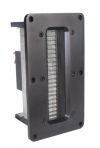
Google an EV t-35 or t-350 horn.
This is a tweeter and by looking at it, the obvious way to mount it is to be wide horizontally and narrow vertically and this is how most were mounted.
On the other hand, because of "pattern flip", the correct way to mount it is up and down because below about 10KHz, the pattern was "flipped" to the opposite of what it looks like.
The problem is MANY horns were made that way and some still are and there is a danger in adding a horn to your ribbon unless you avoid this misbehavior.
You have a source which by itself will become narrower in the vertical as the frequency increases but has little directivity in the horizontal.
Don's formula also puts one in the ball park here. So lets say one had a 12 inch ribbon and what is the approximate vertical pattern angle at 15Khz? By substituting frequency and dimension you get angle of 5.5 degrees.
The problem one has is not up high but lower down where you loose pattern control.
So lets say your crossover is 1KHz and the ribbon is 12 inches tall, now the radiation angle would be about 83 degrees.
So here is where you want to end up. The source is large enough to confine the vertical radiation angle at 1 KHz to about 83 degrees, this means there is no point in having a horn 83 degrees or more and one could use the horn to maintain a smaller vertical angle..
For fun, lets say your vertical horn wall angle is 40 degrees so for the first octave, you have horn controlled vertical.
To avoid pattern flip one needs the dimension of the H and V to be correct and it's an inconvenient relationship.
Lets say your V angle is 40 degrees and your H angle is (to make it easy) 80 degrees. To avoid pattern flip, the horn mouth needs to be twice the height of the mouth width (and exactly the opposite proportions of the t-35 horn). This you can figure this shape out with some paper and protractor.
The up side if this is the throat into the final flare is a slot shape which you happen to have.
One can follow the "rules" and avoid pattern flip and make something with even a 10:1 difference in pattern angles and not have interference, here is a speaker with 10 degrees of vertical, the "how" explained by Doug Jones (made the LEDR recordings).
An impromptu recording of an early SBH-10
Hope that helps
Tom