Punter
Active Member
- Joined
- Jul 19, 2022
- Messages
- 187
- Likes
- 1,010
In any well designed HiFi amplifier, there will be a power supply whose job is to convert the AC mains supply voltage to a DC voltage. The power supply must also be able to provide a reserve of power to cope with any sharp transients in current demand without suffering a decrease in voltage output. So ultimately, the primary characteristic needed is stability, all things considered, the power supply should have no effect on the amplified audio by way of fluctuations in DC potential available to the amplifier circuitry. Practical power supplies for HiFi amplifiers could be linear, switch mode or (less practically) batteries. Most purists would opt for a linear power supply as it eschews any devices that could potentially induce electromagnetic noise into the amplifier circuit itself. Indeed, the linear style supply is by far the most common so that is the one that this treatise will concentrate on.
The linear power supply consists of three main component blocks:
Transformer
Rectifier
Capacitor/s

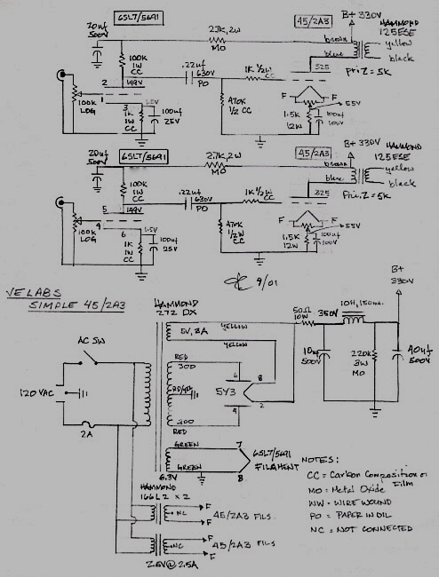
As can be seen from the circuit, the linear supply is quite simple and easy to understand. The one pictured has a positive and negative supply with respect to earth which is normal for HiFi applications. The configuration pictured has a potential swing of 70 volts which is around the average and the power output would be around 300W RMS based on the 500VA secondary on the transformer. Bear in mind that this power figure has to supply both left and right channels so that would mean a practical 100-130 W per channel depending on speaker impedance, leaving some headroom.
Looking at the circuit from left to right;
Transformer primary
Transformer core
Transformer secondary
C1, C9 - X2 Mains rated “snubber” capacitor to filter out EMI
DB1, DB2 - Full wave bridge rectifier
C2, C10 - EMI filter capacitor
C3, C10 - Smoothing capacitors
R1, R3 - Coupling resistors
C4, C5, C6, C12 C13, C14 - Smoothing / Reservoir capacitors
R2, C7, R4, C15 - EMI filter capacitor
C8, C16 - Bypass capacitor
The only component not illustrated is the mains fuse which for this supply would be 5 amp.
The most prominent group of passive components in this design are the smoothing capacitors. As the output of the full-wave rectifier is basically a series of peaks running at 2X the mains frequency, the smoothing capacitors have the job of filtering the peaks out and creating DC voltage.

The EMI filter and bypass capacitors are intended to ground any high frequency components that escape the smoothing capacitors.
Mains voltage is meant to be a pure sine wave but in reality it is very “dirty” and distorted. The reference to “dirty” is to describe the presence of noise, switching pulses and other factors which damage the sine wave in its journey through the power transmission system.

It’s a pretty ugly sinewave. Other distortions come from the load on the power network. Interestingly, the proliferation of switch mode power supplies has actually caused a flattening of the peak of the waveform in most countries. However, once the rectified waveform has been smoothed, the only possible artefact of the rectified waveform will be a component known as “ripple” which can be measured using an AC coupled oscilloscope or voltmeter. In a properly designed power supply, ripple will be a tiny vestige, millivolts at most, riding on the flat line of DC voltage.
One last factor pertaining to components is the transformer itself. There are two types of transformer suitable for use in a HiFi power supply. The traditional EI transformer with an iron core/frame and the toroidal transformer which has a ferrite donut as a core. “EI” refers to the physical construction of the transformer, soft iron laminations in the shape of a capital “E” form the bulk of the core and an additional stack of laminations shaped like a capital “I” is bonded to the end of the “E” to complete the magnetic circuit. In the EI transformer, the primary and secondary windings are stacked on the central part of the “E” usually separated by an insulator. In the toroid, the primary and secondary are overlaid by winding enamelled wire around the toroid with the windings passing through the middle of the toroid. Once again, an insulator will be included between the two layers of windings.
There’s been plenty written about transformers in HiFi power supplies but in reality, the reason for choosing one transformer type over the other would come down to packaging. Toroids really took off when amplifiers (and other equipment) began to move into more compact enclosures. Outside of that, a final consideration would be the transformers tolerance to DC on the mains supply. Toroids don’t cope as well as EI transformers in this respect but DC isn’t a big problem on modern power networks.
Some additional components in a supply could be some additional voltage regulators for peripheral devices and maybe a “soft start” circuit to limit inrush current when the device is turned on. Power supplies using toroid transformers can benefit from soft start as the inrush current can be much higher than an EI transformer.
From a physical design standpoint, the power supply should be located in such a way that it has the least opportunity to induce hum into the amplifier circuit particularly in an integrated amplifier where there is a preamp handling low level signals (like a phono input). It is most critical that the mains inlet and transformer are located as far as practical from sensitive, high-gain inputs.
The circuit shown for this example is somewhat over engineered but the author of the circuit wanted to get the cleanest DC possible, hence the proliferation of EMI filtering components and to a certain extent, considering the power required, the amount of capacitance is fairly hefty. Subsequently, the supply shown will have ample headroom, low ripple and a practical absence of EMI. This is all you need from an AC/DC power supply and any properly designed HiFi amplifier will have such a supply, particularly if the unit is of the “high end” variety.
Based on an understanding of the purpose of an amplifier power supply and it’s electrical operation, how can anyone have any kind of confidence that the expensive mains cable they just purchased will have any effect whatsoever on the working of the power supply and then, by dint, the operation of the amplifier? Yet we have gushing testimonials like this:
“With Ansuz D-TC Supreme all tracks felt like heavily reworked noticeably better versions of themselves. Caetano Veloso’s minimalist take on “Come As You Are” originally by Nirvana was executed in atmospheric, vibrant and artful fashion by both contestants, but the Ansuz’s wobble trimming made it more composed. Interestingly this excess bass output previously remained undetected on my radar, so its reduction was new, instantly noticeable and highly appreciated, but the Dane’s star shined the brightest on three dimensional instrumental and vocal frames. It set these utmost distinct virtual projections within a deeper layer-wise more complex environment than that of C-MARC’s to net a more tangible and quite frankly spectacular here and now effect beyond the latter’s reach. Personal tastes and voicing biases aside, a cable’s ability to morph cameral studio-like recordings into immersive lifelike acts is insanity on its own two legs. “

 hifiknights.com
For €36’000, I think I’d also want this cable to wash my car and walk the dog!

Let us not forget that if the amplifier in the system is properly constructed it will have simple wire fuses in the mains circuit. These will be inside the amplifier enclosure and, in the case of the UK, there will also be one in the mains plug. If a fuse or fuses are not present, then that would mean that the power supply does not meet the code for electrical appliances ANYWHERE IN THE WORLD. Subsequently, the power cable can be any specification you like. It can have the fattest conductors and pointless shielding, fancy braid, palladium prongs and lashings of heat-shrink but still, the power applied to the supply must pass through a single filament of wire in the fuse which is probably around 0.2mm in diameter with a cross sectional area of 0.0314mm² . This is unavoidable without bypassing the fuses, thus rendering the device potentially hazardous (not to mention an insurance liability). Logically, how can the ringing endorsement above be the result of anything but confirmation bias? Nothing downstream of the fuse wire or upstream of the wall plate has been changed by the installation of a massively over specified mains cable. Let’s be clear, the “high-end” mains cable has to perform its magic through a single filament of wire 0.2mm in diameter.

N.B. This is the article I posted on the Steve Hoffman forums for anyone that missed it.
The linear power supply consists of three main component blocks:
Transformer
Rectifier
Capacitor/s
As can be seen from the circuit, the linear supply is quite simple and easy to understand. The one pictured has a positive and negative supply with respect to earth which is normal for HiFi applications. The configuration pictured has a potential swing of 70 volts which is around the average and the power output would be around 300W RMS based on the 500VA secondary on the transformer. Bear in mind that this power figure has to supply both left and right channels so that would mean a practical 100-130 W per channel depending on speaker impedance, leaving some headroom.
Looking at the circuit from left to right;
Transformer primary
Transformer core
Transformer secondary
C1, C9 - X2 Mains rated “snubber” capacitor to filter out EMI
DB1, DB2 - Full wave bridge rectifier
C2, C10 - EMI filter capacitor
C3, C10 - Smoothing capacitors
R1, R3 - Coupling resistors
C4, C5, C6, C12 C13, C14 - Smoothing / Reservoir capacitors
R2, C7, R4, C15 - EMI filter capacitor
C8, C16 - Bypass capacitor
The only component not illustrated is the mains fuse which for this supply would be 5 amp.
The most prominent group of passive components in this design are the smoothing capacitors. As the output of the full-wave rectifier is basically a series of peaks running at 2X the mains frequency, the smoothing capacitors have the job of filtering the peaks out and creating DC voltage.
The EMI filter and bypass capacitors are intended to ground any high frequency components that escape the smoothing capacitors.
Mains voltage is meant to be a pure sine wave but in reality it is very “dirty” and distorted. The reference to “dirty” is to describe the presence of noise, switching pulses and other factors which damage the sine wave in its journey through the power transmission system.
It’s a pretty ugly sinewave. Other distortions come from the load on the power network. Interestingly, the proliferation of switch mode power supplies has actually caused a flattening of the peak of the waveform in most countries. However, once the rectified waveform has been smoothed, the only possible artefact of the rectified waveform will be a component known as “ripple” which can be measured using an AC coupled oscilloscope or voltmeter. In a properly designed power supply, ripple will be a tiny vestige, millivolts at most, riding on the flat line of DC voltage.
One last factor pertaining to components is the transformer itself. There are two types of transformer suitable for use in a HiFi power supply. The traditional EI transformer with an iron core/frame and the toroidal transformer which has a ferrite donut as a core. “EI” refers to the physical construction of the transformer, soft iron laminations in the shape of a capital “E” form the bulk of the core and an additional stack of laminations shaped like a capital “I” is bonded to the end of the “E” to complete the magnetic circuit. In the EI transformer, the primary and secondary windings are stacked on the central part of the “E” usually separated by an insulator. In the toroid, the primary and secondary are overlaid by winding enamelled wire around the toroid with the windings passing through the middle of the toroid. Once again, an insulator will be included between the two layers of windings.
There’s been plenty written about transformers in HiFi power supplies but in reality, the reason for choosing one transformer type over the other would come down to packaging. Toroids really took off when amplifiers (and other equipment) began to move into more compact enclosures. Outside of that, a final consideration would be the transformers tolerance to DC on the mains supply. Toroids don’t cope as well as EI transformers in this respect but DC isn’t a big problem on modern power networks.
Some additional components in a supply could be some additional voltage regulators for peripheral devices and maybe a “soft start” circuit to limit inrush current when the device is turned on. Power supplies using toroid transformers can benefit from soft start as the inrush current can be much higher than an EI transformer.
From a physical design standpoint, the power supply should be located in such a way that it has the least opportunity to induce hum into the amplifier circuit particularly in an integrated amplifier where there is a preamp handling low level signals (like a phono input). It is most critical that the mains inlet and transformer are located as far as practical from sensitive, high-gain inputs.
The circuit shown for this example is somewhat over engineered but the author of the circuit wanted to get the cleanest DC possible, hence the proliferation of EMI filtering components and to a certain extent, considering the power required, the amount of capacitance is fairly hefty. Subsequently, the supply shown will have ample headroom, low ripple and a practical absence of EMI. This is all you need from an AC/DC power supply and any properly designed HiFi amplifier will have such a supply, particularly if the unit is of the “high end” variety.
Based on an understanding of the purpose of an amplifier power supply and it’s electrical operation, how can anyone have any kind of confidence that the expensive mains cable they just purchased will have any effect whatsoever on the working of the power supply and then, by dint, the operation of the amplifier? Yet we have gushing testimonials like this:
“With Ansuz D-TC Supreme all tracks felt like heavily reworked noticeably better versions of themselves. Caetano Veloso’s minimalist take on “Come As You Are” originally by Nirvana was executed in atmospheric, vibrant and artful fashion by both contestants, but the Ansuz’s wobble trimming made it more composed. Interestingly this excess bass output previously remained undetected on my radar, so its reduction was new, instantly noticeable and highly appreciated, but the Dane’s star shined the brightest on three dimensional instrumental and vocal frames. It set these utmost distinct virtual projections within a deeper layer-wise more complex environment than that of C-MARC’s to net a more tangible and quite frankly spectacular here and now effect beyond the latter’s reach. Personal tastes and voicing biases aside, a cable’s ability to morph cameral studio-like recordings into immersive lifelike acts is insanity on its own two legs. “
Ansuz D-TC Supreme – HiFi Knights
This is the www.hifiknights.com review of Ansuz D-TC Supreme power cable. Author: Dawid Grzyb. Enjoy!
hifiknights.com
For €36’000, I think I’d also want this cable to wash my car and walk the dog!
Let us not forget that if the amplifier in the system is properly constructed it will have simple wire fuses in the mains circuit. These will be inside the amplifier enclosure and, in the case of the UK, there will also be one in the mains plug. If a fuse or fuses are not present, then that would mean that the power supply does not meet the code for electrical appliances ANYWHERE IN THE WORLD. Subsequently, the power cable can be any specification you like. It can have the fattest conductors and pointless shielding, fancy braid, palladium prongs and lashings of heat-shrink but still, the power applied to the supply must pass through a single filament of wire in the fuse which is probably around 0.2mm in diameter with a cross sectional area of 0.0314mm² . This is unavoidable without bypassing the fuses, thus rendering the device potentially hazardous (not to mention an insurance liability). Logically, how can the ringing endorsement above be the result of anything but confirmation bias? Nothing downstream of the fuse wire or upstream of the wall plate has been changed by the installation of a massively over specified mains cable. Let’s be clear, the “high-end” mains cable has to perform its magic through a single filament of wire 0.2mm in diameter.
N.B. This is the article I posted on the Steve Hoffman forums for anyone that missed it.
Last edited:

")