• WANTED: Happy members who like to discuss audio and other topics related to our interest. Desire to learn and share knowledge of science required. There are many reviews of audio hardware and expert members to help answer your questions. Click here to have your audio equipment measured for free!

step response is a important part to show speed of speaker that is good enough for ITD. See measures

Status
Not open for further replies.
OP
B

bennybbbx

Addicted to Fun and Learning
Joined
May 27, 2020
Messages
691
Likes
124
Location
germany
??? The difference is there is a time delay and tiny amplitude difference between the signals picked up by the 2 mics. No difference in the frequency composition.

with a time delay both stereo speakers can not play the same. when the girl sing at frequency 400 hz and it is at same time hear in both speakers then there is no delay and it sound as mono. often in music is used a ping pong delay. please look in this video you can hear it. it is an example with long delay time. so hear clear left and right speaker need play diffrent frequency. hear at 7 mind 20


this is a long delay but in most music or reverb it is short and not so easy hear. esult is same. left and right speaker play in stereo difffrent signals frequency and levels.
 
Last edited:

markus

Addicted to Fun and Learning
Joined
Sep 8, 2019
Messages
681
Likes
785
see groupdelay plots from speakers or headphones. the delay at frequency is diffrent.

Still fixed for each frequency and therefore there isn't possibly any effect on ITD whatsoever.

the speaker need some time to reach the level, need brake and need speed up in other direction. this give a input lag or shown in group delay.

Not really. GD comes from passing a signal through a filter.
 
Last edited:

NTK

Major Contributor
Forum Donor
Joined
Aug 11, 2019
Messages
2,708
Likes
5,978
Location
US East
with a time delay both stereo speakers can not play the same. when the girl sing at frequency 400 hz and it is at same time hear in both speakers then there is no delay and it sound as mono. often in music is used a ping pong delay. please look in this video you can hear it. it is an example with long delay time. so hear clear left and right speaker need play diffrent frequency. hear at 7 mind 20


this is a long delay but in most music or reverb it is short and not so easy hear. esult is same. left and right speaker play in stereo difffrent signals frequency and levels.
Well, of course they cannot be playing the same sound simultaneously, because there is a time delay between them. We are not talking about simultaneous sound, we are talking about ITD, and how/why would the ITD change?

The video talks about adding (a series of) delays artificially. I don't understand what adding artificial delays has to do with this discussion. Of course they alter the perception of the sound. That's what they are for.
 

audio2design

Major Contributor
Joined
Nov 29, 2020
Messages
1,769
Likes
1,830
Friend hand an expression, "He is like a black hole with a black wall around it. Nothing gets in. Nothing gets out."

Now who is the foolish one, the person who does not get it, of the people who didn't realize that would be the situation on page 1 or 2 and still are at it on Page 11? :)

When trying to educate my children, helping with other children, and even academia, there was a concept of "educational maturity". It represents a certain maturity that one must have reached in order to be educated. Once someone hits that level, education is much easier. Before that it will be a struggle and likely pointless.
 

thewas

Master Contributor
Forum Donor
Joined
Jan 15, 2020
Messages
6,877
Likes
16,847
51izJizGmAL._AC_SY450_.jpg

Source of image: https://www.amazon.com/Pictura-Decetis-Humorous-Masculine-Birthday/dp/B07P833KL3
 
OP
B

bennybbbx

Addicted to Fun and Learning
Joined
May 27, 2020
Messages
691
Likes
124
Location
germany
The video talks about adding (a series of) delays artificially. I don't understand what adding artificial delays has to do with this discussion. Of course they alter the perception of the sound. That's what they are for.

in this video you can hear that left speaker play diffrent frequency or signal or transient than right speaker. this diffrent frequency results in group delay diffrence depend on group delay plot of the speaker. the transients between left and right speakers also not have same timing. they are shift. you need understand that transients occur also from the reverb reflections. i have a convolution reverb this have a stretch parameter. so can slowdown the reverb alot. then you can more clear hear the transients of the reverb early reflections. should i do a video ?. then can more clear hear that left and right speaker play diffrent frequency. there can also mix together 2 transients or wave of diffrent frequency. the transients then play with a wrong time delay between them
 
Last edited:
OP
B

bennybbbx

Addicted to Fun and Learning
Joined
May 27, 2020
Messages
691
Likes
124
Location
germany
Not really. GD comes from passing a signal through a filter.

the speaker act as a HP or LowPass Filter too. for example a speaker with a play range -3 db 100 hz-5 khz is a bandpass filter. and the steep depend on speaker characteristic. and so it do group delay and phase shifts too
 

markus

Addicted to Fun and Learning
Joined
Sep 8, 2019
Messages
681
Likes
785
the speaker act as a HP or LowPass Filter too. for example a speaker with a play range -3 db 100 hz-5 khz is a bandpass filter. and the steep depend on speaker characteristic. and so it do group delay and phase shifts too
Bingo! But the specific characteristics of that filter (mechanical or electrical) still do not change over time ;) And therefore – wait for it – no change in ITD.
 
Last edited:
OP
B

bennybbbx

Addicted to Fun and Learning
Joined
May 27, 2020
Messages
691
Likes
124
Location
germany
Bingo! But the specific characteristics of that filter (mechanical or electrical) still do not change over time ;) And therefore – wait for it – no change in ITD.

it change depend on frequency. and this can see in group delay and phase. the phase show the error from input in degree. that left and right speaker play diffrent frequency you can hear in this convolution reverb audio example. look at the stretch knob in thid video. first reverb is full off. dry sound. then i switch the reverb on


it contain only 3 drum sounds, so the reverb reflections can better detect when stretch. but of course compley music there are much more reflections of diffrent frequency. with low % stretch value you get a room sound. with higher stretch hear only clicks at diffrent freq left and right. i hope it is clear, or need a more stretched impulse response of the room ?

because the left and right reflections of diffrent frequency that come from speaker the brain need to create a room feeling. ITD is important for low frequency, because reverb is mostly in range from 150 hz upto 2 khz. and with slow speakers it do more jitter and because ITD can hear from 10 µsec this jitter of slow speakers give wrong room sound
 

markus

Addicted to Fun and Learning
Joined
Sep 8, 2019
Messages
681
Likes
785
it change depend on frequency. and this can see in group delay and phase. the phase show the error from input in degree. that left and right speaker play diffrent frequency you can hear in this convolution reverb audio example. look at the stretch knob in thid video. first reverb is full off. dry sound. then i switch the reverb on


it contain only 3 drum sounds, so the reverb reflections can better detect when stretch. but of course compley music there are much more reflections of diffrent frequency. with low % stretch value you get a room sound. with higher stretch hear only clicks at diffrent freq left and right. i hope it is clear, or need a more stretched impulse response of the room ?

because the left and right reflections of diffrent frequency that come from speaker the brain need to create a room feeling. ITD is important for low frequency, because reverb is mostly in range from 150 hz upto 2 khz. and with slow speakers it do more jitter and because ITD can hear from 10 µsec this jitter of slow speakers give wrong room sound
OK bennybbbx, you continue to demonstrate that you're incapable of understanding the topic. No amount of posts here seem to help the slightest. You also refuse to read anything that has been suggested to you. So it's probably best that I stop wasting my time here. Goodbye for now.

P.S. Wake me up when you're ready to actually learn something. Here's again a list of books you should have read by then:

- Howard/Angus, "Acoustics and Psychoacoustics"
- D'Appolito "Lautsprecher-Messtechnik"
- Toole, "Sound Reproduction"

Also recommended:
- Dickason, "Lautsprecherbau"
- Everest, "Master Handbook of Acoustics"
 
OP
B

bennybbbx

Addicted to Fun and Learning
Joined
May 27, 2020
Messages
691
Likes
124
Location
germany
OK bennybbbx, you continue to demonstrate that you're incapable of understanding the topic. No amount of posts here seem to help the slightest. You also refuse to read anything that has been suggested to you. So it's probably best that I stop wasting my time here. Goodbye for now.

P.S. Wake me up when you're ready to actually learn something. Here's again a list of books you should have read by then:

- Howard/Angus, "Acoustics and Psychoacoustics"
- D'Appolito "Lautsprecher-Messtechnik"
- Toole, "Sound Reproduction"

Also recommended:
- Dickason, "Lautsprecherbau"
- Everest, "Master Handbook of Acoustics"

thats only a bash against me without Facts . Have you really hear my audio example and not notice that left and right speaker play diffrent frequency content at same time ?. so jitter happen between left and right speaker due to diffrent group delay depend on frequency. this is what i hear as less stereo width or wrong room sound. I get bad feeling when hear in db(C) above 80 db or db(a) 72 db . so i never hear above 80 db. but many like hear loud look here. https://www.cdc.gov/nceh/hearing_loss/what_noises_cause_hearing_loss.html

many people hear 100 db and in clubs and concerts or in headphones. in germany since 2007 is a DIN Limit to 100 db. and they write with 100 db hearing loss possible after 15 minutes. with 105 db- 110 db loss possible after 5 minutes. maybe some can resist double time. thats 30 minutes. but can you really confirm that the writers of the books and the speaker developer have good ITD hearing ability ?

and BTW: You tell that my Kali Group delay measure should not be valid. but look at my group delay and the distortion levels of the Kali LP6 here. You see a distortion peak at 650 hz in Amirs measure where my measure show the bad group delay valley. so seem my group delay measure seem good enough
https://www.audiosciencereview.com/forum/index.php?threads/kali-lp-6-review-studio-monitor.17978/

maybe look at distortion show too if a speaker is good for ITD. On kali distortion increase alot after 1 khz maybe this indicate too slow bass/mid.

and here i find a measure with a bad step response. have less bass as the JBL 104, so should look much faster

 
Last edited:

RayDunzl

Grand Contributor
Central Scrutinizer
Joined
Mar 9, 2016
Messages
13,247
Likes
17,163
Location
Riverview FL
other people write theory and do not confirm how many % the step response change when increase Bass by 15 db. i do tests also with phase linear filters and notice change of 15 db in FR cause only 12 % of longer step response.

Longer step is a result of lower frequency extension.

Using a low cutoff of 10Hz, measured at the amplifier, 100ms "decay". 5Hz would double that to 200ms. DC would make a flatline at the peak.

index.php
 
OP
B

bennybbbx

Addicted to Fun and Learning
Joined
May 27, 2020
Messages
691
Likes
124
Location
germany
Longer step is a result of lower frequency extension.

Using a low cutoff of 10Hz, measured at the amplifier, 100ms "decay". DC would make a flatline at the peak.

index.php

yes i know, at very low freq (below 30 hz)length is increase much, but overall a longer step let sound the speaker not so good i hear. If this is result of the corossover filter or speaker is not important at the end result. maybe step responses should do with a 100 hz HP filter before. so reduce alot influence of bass range.

see here the step response of this speaker. it go very low and is big. but step response look fast


as a impulse response this look not, because can see the longer decay time of 0.5 ms. it look as a inverted step response

but a smaller speaker get smaller step response. but it is not so much.


here can see my measure with lots bassboost. also not so much increase of step response. the kali with less bass than the JBL bassboost have much longer step response

 
OP
B

bennybbbx

Addicted to Fun and Learning
Joined
May 27, 2020
Messages
691
Likes
124
Location
germany
A better test that show that the FR diffrence do no change in Step Response only phase shifts from filters do. create a fake calibration profile that boost bass much. but the step response did not change. you can verify my test easy in REW or other. just create a fake microphone profile that have for example at 30 hz -15 db. then select it in rew and because ypour microphone have not so much bass loss you see 15 db more bass in your FR but step response is not change,


diffrent calibration file (2).jpg
diffrent calibration file 2.jpg


step response same.jpg


diffrent FR.jpg
 

Shazb0t

Addicted to Fun and Learning
Joined
May 1, 2018
Messages
643
Likes
1,231
Location
NJ
Blah blah blah
11 pages of people explaining to you why your theories and understandings are wrong. We get it, you refuse to change your mind! At this point though, what purpose does it serve to keep bumping your own thread? Clearly nothing is going to change your mind here. Please give it a rest.
 
Last edited:
OP
B

bennybbbx

Addicted to Fun and Learning
Joined
May 27, 2020
Messages
691
Likes
124
Location
germany
11 pages of people explaining to you why your theories and understandings are wrong. We get it, you refuse to change your mind! At this point though, what purpose does it serve to keep bumping your own thread? Clearly nothing is going to change your mind here. Please give it a rest.

wy i should not post this. this is important. first i thougt ok a little the FR change. But my tests confirm that the step response do not change with diffrent FR when use no EQ and use another calibration file. try it out. just use a diffrent microfone calibration file and do a new measure
 

dominikz

Addicted to Fun and Learning
Forum Donor
Joined
Oct 10, 2020
Messages
803
Likes
2,630
wy i should not post this. this is important. first i thougt ok a little the FR change. But my tests confirm that the step response do not change with diffrent FR when use no EQ and use another calibration file. try it out. just use a diffrent microfone calibration file and do a new measure
I know I said not to post here anymore, but this is just too wrong and I had to react. :) So one last post:

REW manual ("Impulse Graph" chapter) explicitly states that the software does not take into account the calibration file for the impulse/step response view:
1639950620352.png

So of course you see no change there if you use a different calibration file - the REW software doesn't take the calibration file into account at all when calculating the impulse and step response in the first place! :D

On the other hand if you apply such boosts via EQ (which is then actually applied to the recorded data and therefore affects all of the views), the step response naturally changes as expected:
index.php

1639948329404.png
1639948365497.png


In short - no surprises, linear systems theory is once again 100% predictive of such effects :)
 
Last edited:
OP
B

bennybbbx

Addicted to Fun and Learning
Joined
May 27, 2020
Messages
691
Likes
124
Location
germany
I know I said not to post here anymore, but this is just too wrong and I had to react. :) So one last post:

REW manual ("Impulse Graph" chapter) explicitly states that the software does not take into account the calibration file for the impulse/step response view:
View attachment 173473
So of course you see no change there if you use a different calibration file - the REW software doesn't take the calibration file into account at all when calculating the impulse and step response in the first place! :D

ok, i verify this with arta soon what happen there. EDIT: Arta too ignore the calibratiomn file for step response, It is intresting to know how much the step response change without use a EQ.

I read the manual of REW and i read that it can create a minimum Phase IR from measure. This is maybe the result of the FR and a good speaker should look as this. and my conclusion is any increase of this is because of slow speaker. see here the compare

EDIT: I get in mind this first post compare was wrong because the compare must be between impulse response and minumum phase IR. I remove the overlay and post the correct overlay. i think measure software should output minimum phase step response too. and arghhh there stand in REW manual that the calibration file can add to create minimal phase IR. but it need switch off i guess.

If Include cal file effects is selected the response used to generate the minimum phase will include any calibration files the measurement has. That means their influence will become part of the minimum phase impulse response. Note that measurement impulse responses themselves do not include cal file effects.

The MTM seem have problem with the 2 woofers/mid that play the same. and the JBL 104 is hard to comparable because it is coaxial. the most precise speakers seem the celestion 10 inch guitar speaker(which is a design from 1960 around) and the Eris 3.5. measures are 1.5 cm away from woofer. on the MTM and jbl 104 BT it is maybe 1-2 cm more because they have a grill

the celestion 10 inch guitar box
celestion 10 inch speaker minimum phase impulse overlay.jpg


the presonus eris 3.5. it look so good because the woofer can do more than 6 khz -3 db. with + 10 db EQ it can work as wide band speaker upto 13 khz when remove the tweeter
eris 3.5 minimum phase impulse overlay.jpg


The Kali LP 6 1. version

kali lp6 1. wave minimum phase impulse overlay.jpg


the others i have attached too below

if the calibration file is ignore by create of the step response this is very bad. because a microphone can give much diffrent FR.

the calibration file of the arc 2.5 mems microphone is this

30.0 -9
40.0 -7
50.0 -5.0
60.0 -4.0
70.0 -2.5
80.0 -2.0
130.0 -1.0
200.0 0.5
300.0 1.0
400.0 1.0
500.0 1.0
700.0 1.0
800.0 1.0
1000.0 0.5
2000.0 0
2400.0 0.3
3000.0 1.0
6000.0 1.6
10000.0 3.8
20000.0 6.5

the fake calibration file for more bass test was this

30.0 -15
50.0 -10.0
60.0 -9.0
70.0 -2.5
80.0 -2.0
130.0 -1.0
200.0 0.5
300.0 1.0
400.0 1.0
500.0 1.0
700.0 1.0
800.0 1.0
1000.0 0.5
2000.0 0
2400.0 0.3
3000.0 1.0
6000.0 1.6
10000.0 3.8
20000.0 6.5

my sonarworks xref 20 microphone have not much diffrence in bass but the xref 20 is unidirectional and have much more noise as the mems microphone. for near field measure unidrectional is not so good, because recognize more reflections from side and back. ears are too not unidirectional. so i use mems microphone always. then mems have 4-6 damping on side and back.

20.0 0.01
20.5 0.01
20.9 0.01
21.4 0.02
21.9 0.02
22.4 0.02
23.0 0.03
23.5 0.03
24.1 0.04
24.6 0.04
25.2 0.05
25.8 0.05
26.4 0.06
27.0 0.06
27.6 0.07
28.3 0.07
28.9 0.08
29.6 0.08
30.3 0.08
31.0 0.09
31.7 0.09
32.5 0.10
33.2 0.10
34.0 0.11
34.8 0.11
35.6 0.12
36.5 0.12
37.3 0.13
38.2 0.13
39.1 0.14
40.0 0.14
40.9 0.15
41.9 0.15
42.9 0.16
43.9 0.16
44.9 0.17
45.9 0.17
47.0 0.17
48.1 0.18
49.2 0.18
50.4 0.19
51.6 0.19
52.8 0.20
54.0 0.20
55.3 0.21
56.6 0.21
57.9 0.22
59.2 0.22
60.6 0.23
62.0 0.23
63.5 0.23
65.0 0.24
66.5 0.24
68.0 0.23
69.6 0.23
71.3 0.22
72.9 0.21
74.6 0.20
76.4 0.18
78.2 0.17
 

Attachments

  • jbl 104 mimimum phase impulse overlay.jpg
    jbl 104 mimimum phase impulse overlay.jpg
    252.7 KB · Views: 58
  • iloud mtm minimum phase impulse overlay.jpg
    iloud mtm minimum phase impulse overlay.jpg
    249.4 KB · Views: 52
Last edited:
OP
B

bennybbbx

Addicted to Fun and Learning
Joined
May 27, 2020
Messages
691
Likes
124
Location
germany
another intresting when show step response with or without Kali LP6 as sub there is no step response increase. if the FR is really important to step response question is wy does the step response decay not increase to the much longer kali step response decay because the Kali do the lower bass ?. and wy does with this much bass enhance the step response decay does only so little change ? . with this test results i come to conclusion the step response change when use EQ happen only because of phase shift EQ do. the measure is done at hearing position around 50 cm away from JBL and around 1.5 meter away from kali. i do time align the Kali and the JBL in the DSP. jbl need a delay of 7.5 ms

jbl 104 no kali as sub.jpg
jbl 104 kali as sub.jpg
 
Last edited:

kyle_neuron

Active Member
Joined
Jun 18, 2021
Messages
149
Likes
254
For the third time. Both of your microphones are omnidirectional. This is stated by the manufacturers of both microphones themselves.

Neither of them are ‘unidirectional’, as this would be a literal laser beam.

with this test results i come to conclusion the step response change when use EQ happen only because of phase shift EQ do..

Incorrect. Here is an example. I measured a single Faital Pro 3FE22 driver resting on it's box on my desk, with an Earthworks M30 microphone at 10 centimetres, using an 87.4 second stimulus with the AFMG EASERA TDS module. No post-processing windowing is applied.

Due to the way Time Delay Spectrometry works, we can consider this to be about as a reflection-free measurement as possible in the circumstances.

I then duplicated the trace, and edited the data directly to set the magnitude from 30 Hz to 200 Hz to a flat value at 91 dB. Markers are added to the traces to show the level increase over the original measurement.
1640837244728.png


This modification is linear phase, as you can see here in the phase trace of both data sets. The same cursors are visible, confirming identical phase at the adjusted frequencies:
1640837320863.png


Here are the two impulse responses, overlaid
1640837467864.png


You can barely see the shift in the blue modified data, so here it is zoomed in. The later part of the IR deviates more, as you'd expect from increased energy.
View attachment 175442

And here we have the two step responses. Again, blue trace is the artificially modified magnitude response with much more energy in the sub region, but no change in phase:
1640837632945.png


Bonus round - to echo what @gnarly has said, step response is not a good way to do time alignment of sources. Again, an example. This time, a four way system, with a passive full-range speaker (blue), a low frequency speaker (green), and a subwoofer (red). I have already applied EQ, and appropriate high pass and low pass filters; all 4th order, asymmetrical electrical slopes.

Magnitude responses solo:
1640838691332.png


I have also already time-aligned each speaker, at the listening position, using delay, polarity inversions and all-pass filters based on the phase trace. This is commonly accepted practice for speaker alignment. Here are the individual pass band phase traces after alignment:
1640838788084.png

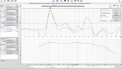
And the magnitude responses again, but this time with the sum trace of all speakers playing together in black:
1640838864737.png


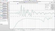
Now I'm not posting these to show off. The point is that this is a pretty damn good alignment. Yet, here are the step responses for each speaker with the alignment in place:
1640838942138.png

Zoomed in:
1640838977240.png


Just for completeness sake, the sum response with combined group delay:
1640839196890.png


Can you honestly say you'd have arrived at a similar result using just the step response? If so, what would your method be? Here's the starting point of each speaker, with the EQ (I'm not cruel...) but without any high pass or low pass filters.

1640839520149.png


1640839507159.png

1640839496797.png


The raw IR data for each passband is attached in the zip file - channel 2 contains the data. Note they're measured at 3 metres distance, and some elements are horn-loaded. You'll need to consider that when looking for the IR peak.
 

Attachments

  • ASR Step Response alignment test - IR data.zip
    46.5 KB · Views: 61
Last edited:
Status
Not open for further replies.
Top Bottom