• WANTED: Happy members who like to discuss audio and other topics related to our interest. Desire to learn and share knowledge of science required. There are many reviews of audio hardware and expert members to help answer your questions. Click here to have your audio equipment measured for free!

SOTA Pyxi Phono Stage Review

Rate this phono stage:

  • 1. Poor (headless panther)

    Votes: 10 8.3%
  • 2. Not terrible (postman panther)

    Votes: 24 20.0%
  • 3. Fine (happy panther)

    Votes: 67 55.8%
  • 4. Great (golfing panther)

    Votes: 19 15.8%

  • Total voters
    120
For those of you who are really interested in the LF resonant behavior, the above blog entries (all supported by actual measurements using accelerometers etc. as well as cartridge outputs) are very informative. These are part of an extensive somewhat iconoclastic series of evaluations/analyses of various resonant modes and behavior in a PU arm/cartridge system.
So much so that I purchased a measurement system (mostly second hand from ebay) that could more or less duplicate their results, and I have tested various cartridge/arm combinations (including the VPI 3d/Madake combo that I use) for the various resonances with the intention of DSP correcting the response.
In particular note the comments on "modern" cartridges etc. and damping and the relationship of the excitation frequency to the "resonance".
 
Frank - are you using the Puffin or something else? That does seem to be the most effective way to limit the bandwidth and apply accurate RIAA correction.
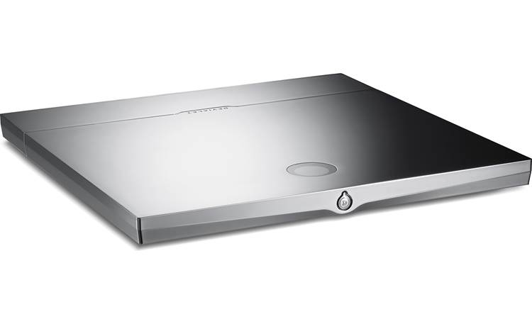
I am using a Devialet amp which can have loads of choices of loading, filtering and weighting several more than RIAA though it is moot since I only have RIAA records. I do use the 1974 RIAA update and the high pass filter, of course.
 
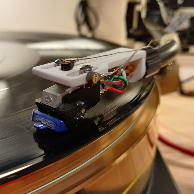
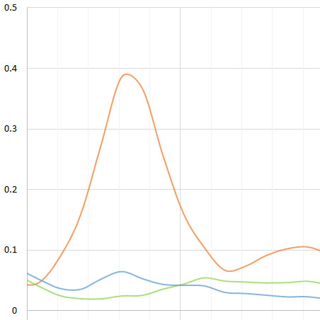
My own tests of combined tonearm+cartridge resonance produce an offset when the compliance of the stylus changes.

AT122EP (suggested tracking force 1.0g-1.8g):

1685713135476.png


Shure M75 w/ Kyowa aftermarket stylus, very stiff suspension intended for tracking @ 1.5-3g IIRC:

1685713229864.png


In the case of the Kyowa, the compliance was low enough that bass on my records was accentuated.
 
For those of you who are really interested in the LF resonant behavior, the above blog entries (all supported by actual measurements using accelerometers etc. as well as cartridge outputs) are very informative. These are part of an extensive somewhat iconoclastic series of evaluations/analyses of various resonant modes and behavior in a PU arm/cartridge system.
So much so that I purchased a measurement system (mostly second hand from ebay) that could more or less duplicate their results, and I have tested various cartridge/arm combinations (including the VPI 3d/Madake combo that I use) for the various resonances with the intention of DSP correcting the response.
In particular note the comments on "modern" cartridges etc. and damping and the relationship of the excitation frequency to the "resonance".
This is what I mean.
Misses the way the seismic sensor works altogether and, despite the data being there, entirely misses the main point.

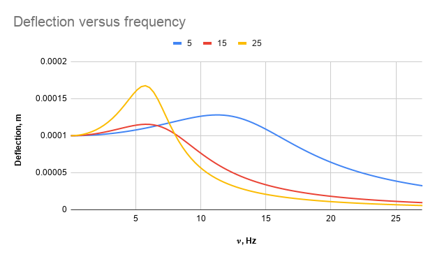
As for damping in modern cartridges being high that is only good for handling (lower resonant peak) but poor for fidelity. High damping shunts the stator to the motor and the frequency at which accurate transduction starts to be realised goes up from ~ 2x natural frequency to higher, ie the accurate bandwidth of the transducer is compromised for handling which happens because the facts of seismic transducers are not taken into account.
Not only does the lowest accurate bass frequency get higher with more damping but, depending on the type of damping, the accuracy is worse at higher frequencies too.
I tried to clip an informative graph from the text but it failed on this iPad for a wrong file type, but it shows deflection with frequency. The transduction only starts to be accurate once the stator displacement is zero (self evidently) and that varies a lot with damping being both further from zero and further up the frequency range before near-accuracy is achieved as damping is increased.
 
I am using a Devialet amp which can have loads of choices of loading, filtering and weighting several more than RIAA though it is moot since I only have RIAA records. I do use the 1974 RIAA update and the high pass filter, of course.
Frank - is this what you have?

 
This is what I mean.
Misses the way the seismic sensor works altogether and, despite the data being there, entirely misses the main point.
Yes. It is like if someone wanted for the speaker driver to provide sound fidelity below its natural resonant frequency. Should it be speaker or seismic sensor, it is all the same.
 
I have the Original d’Atelier which they made in limited number but is identical to the 1000 Pro except for colour.

At $35K for the $1000 Pro - that's what I call "fancy living"! Sounds like an "end game" amplification solution. Cool!
 
I should know better than to enter this fray, but against my better judgement, here goes...

If I understand the various discussions going on, there are a number of propositions:

1. Any audio content below 20Hz whether it was put there on purpose or are just artifacts of the mechanical system are irrelevant to the process of listening and therefore should be removed before the phono pre.

2. Removing the unwanted signal before the phono pre compromises the design of the phono pre and can introduce unwanted distortion and noise. Removing the unwanted signal after the phono pre avoids this, but the damage is already done.

3. It is a simple matter to remove the unwanted signal so why didn't SoTA do this in the first place?

Please feel free to bring any other salient points to my attention if I overlooked anything.

Items 1 & 2 are related with respect to where the removal of the unwanted signal should take place. While putting the filter before the phono pre might prevent distortion by providing additional LF headroom, it comes at the cost of increased noise and loading issues. There was a very good thread on DIYAudio (which I'm unable to locate presently) which posited that large LF excursions of the stylus can create distortion and IM at the cartridge since the behavior of the generator is non-linear at the extremes and therefore attempting to correct for this before or after the phono stage was a fool's errand as the damage is already done no matter where you place a HPF. The best remedy is to prevent excessive LF stylus excursions in the first place by minimizing the source of excitation for arm/cart resonance, i.e. warps or defects in the pressing. Absent that, a good quality HPF after the phono pre can prevent excessive woofer excursion which can actually damage the driver (I blew up 2 rather expensive drivers because of this before I added an 8 pole 18Hz Butterworth HPF to LF path in my bi-amped system).

As to whether this is a simple matter or not is debatable. To do it right would certainly have added cost, complexity and size to the Pyxi and as a number of people are already complaining about the price, it seems logical to have left it out. Many line level preamps and some integrated amps have this feature built in, so maybe this is a better place to address it.

The Schiit Mani has a 2 stage HPF on the outputs that can be switched in/out, each stage being a single pole RC filter with an Fc of ~16Hz. Each stage will have ~6dB/octave attenuation below the cutoff which means switching in the first stage would have ~9dB attenuation at 8 Hz, in other words, completely useless. Switching in both stages improves the rejection at 10Hz to -15dB; better, but still insufficient to be useful. It also moves the -3dB point up to 50Hz where it will start to impact the low bass response. Obviously, there is a down side to being too simple.

The Pyxi was designed to be a entry level (low cost) high spec phono pre that punches way above it's weight; from the initial feedback, it appears that SoTa accomplished their goal fairly well. They are looking at releasing a higher end (more expensive) design that has more bells and whistles and slightly better specs. It's regrettable that a number of people were offended that the power switch, LED and gain switch didn't line up exactly on the front panel, but they are 3 different types of RA PCB mounted components and finding all three that had the exact vertical height proved to be nearly impossible. Interesting that no one complained about the back panel, as the DIP switches, RCA jacks and power input don't line up either. C'est la vie.
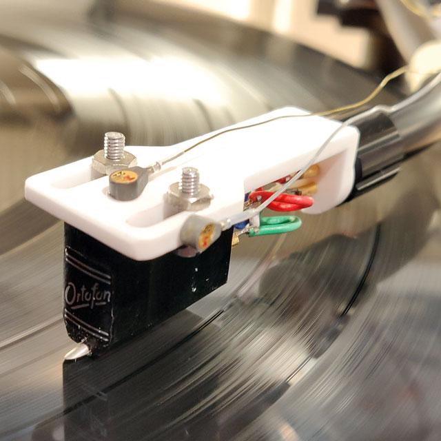
 
Yes. It is like if someone wanted for the speaker driver to provide sound fidelity below its natural resonant frequency. Should it be speaker or seismic sensor, it is all the same.
Indeed!

Surely it is self evident that the cartridge output at resonance is dominated by cartridge body and headshell bouncing not stylus movement?

Surely it is self evident that the cartridge output is only transcribing the stylus movement in the groove once the cartridge body is stationary(ish in reality) relative to the groove?
 
1. Any audio content below 20Hz whether it was put there on purpose or are just artifacts of the mechanical system are irrelevant to the process of listening and therefore should be removed before the phono pre.
The reason it is good engineering practice to remove it has nothing to do with audibility and everything to do with the physics of a seismic type transducer.
Below around 2x the natural frequency of the mass on the compliance too much of the output of the sensor is due to the part of the cartridge which should to be the ”stator” bouncing on the suspension rather than the stylus moving relative to a stationary headshell. At 2x the natural frequency and above the output is acceptably close to being due to stylus movement and has ceased being corrupted by the “stator” not being static.

All the arguments put forward about not having a high pass filter, except it being too expensive, have not been based on the facts, well known 60 years ago when i first took an interest and still well understood when i was involved in the 1970s but apparently forgotten now.
 
The reason it is good engineering practice to remove it has nothing to do with audibility and everything to do with the physics of a seismic type transducer.
Below around 2x the natural frequency of the mass on the compliance too much of the output of the sensor is due to the part of the cartridge which should to be the ”stator” bouncing on the suspension rather than the stylus moving relative to a stationary headshell. At 2x the natural frequency and above the output is acceptably close to being due to stylus movement and has ceased being corrupted by the “stator” not being static.

Yes, I think we all understand the source of the LF "noise"; it really doesn't matter whether the stylus moves while the cart remains stationary or the cart moves while the stylus remains static, the effect is the same regardless of where you place the inertial frame of reference.

It's only good engineering practice to remove it if doing so doesn't create additional undesired side effects (noise or loading issues) or removing the LF signal still leaves the distortion and IM of the inband audio signal due to the generator characteristics as explained above. A better alternative to removing the undesired signal might be to prevent it from occurring in the first place, by using vacuum hold down, a periphery ring, record weight or replacing warped or defective pressings with newer, flatter ones (the LP that damaged my speakers was a Bob Seger pressing that had a noticeable divot in the track "Night Moves"; I've since replaced it and all is well).

Also, removing an unwanted signal may be system dependent with regards to additional noise introduction; when the noise floor is -100dBV any additional noise from an active HPF can compromise the design which may not be the case in another seismic system. Correct me if I'm wrong, but I doubt few designs from the 60's and 70's had this level of performance.
 
Last edited:
Indeed!

Surely it is self evident that the cartridge output at resonance is dominated by cartridge body and headshell bouncing not stylus movement?

Surely it is self evident that the cartridge output is only transcribing the stylus movement in the groove once the cartridge body is stationary(ish in reality) relative to the groove?
Surely it is self-evident there is a possibly mistracking area, audibly useful area and something in between ;).

Trackability.png
 
Yes, I think we all understand the source of the LF "noise"; it really doesn't matter whether the stylus moves while the cart remains stationary or the cart moves while the stylus remains static, the effect is the same regardless of where you place the inertial frame of reference.

It's only good engineering practice to remove it if doing so doesn't create additional undesired side effects (noise or loading issues) or removing the LF signal still leaves the distortion and IM of the inband audio signal due to the generator characteristics as explained above. A better alternative to removing the undesired signal might be to prevent it from occurring in the first place, by using vacuum hold down, a periphery ring, record weight or replacing warped or defective pressings with newer, flatter ones (the LP that damaged my speakers was a Bob Seger pressing that had a noticeable divot in the track "Night Moves"; I've since replaced it and all is well).

Also, removing an unwanted signal may be system dependent with regards to additional noise introduction; when the noise floor is -100dBV any additional noise from an active HPF can compromise the design which may not be the case in another seismic system. Correct me if I'm wrong, but I doubt few designs from the 60's and 70's had this level of performance.
OT question- same Phoenix Engineering guy (John) whom I met many years ago at Peavey?
 
OT question- same Phoenix Engineering guy (John) whom I met many years ago at Peavey?
Sorry, no. PE used to make digital synthesized mains power supplies to drive turntable motors (Falcon, Eagle) and turntable tachometer (RoadRunner).

Wyn did nearly all the circuit design on the Pyxi, I did most of the PCB/mechanical/QC/mfring parts.

Regards,
Bill Carlin
 
  • Like
Reactions: SIY
A better alternative to removing the undesired signal might be to prevent it from occurring in the first place, by using vacuum hold down, a periphery ring, record weight or replacing warped or defective pressings with newer, flatter ones
Correct me if I'm wrong but isn't Frank's point, that the subsonic content is generally not related to record warp, and a periphery ring would not completely eliminate it?
 
The reason it is good engineering practice to remove it has nothing to do with audibility and everything to do with the physics of a seismic type transducer.
Below around 2x the natural frequency of the mass on the compliance too much of the output of the sensor is due to the part of the cartridge which should to be the ”stator” bouncing on the suspension rather than the stylus moving relative to a stationary headshell. At 2x the natural frequency and above the output is acceptably close to being due to stylus movement and has ceased being
Did I eliminate this problem by having a Technics SL-M3 linear tracking T4P mount turntable?
 
Correct me if I'm wrong but isn't Frank's point, that the subsonic content is generally not related to record warp, and a periphery ring would not completely eliminate it?
I won't presume to answer for him, but if not record warp (or LP defects) what is causing the excitation and motion? Acoustic feedback from the speakers usually occurs at a higher frequency than arm/cart resonance (it's usually audible).
 
Back
Top Bottom