OP
Velocipede_Acoustics
Member
- Joined
- Jun 8, 2021
- Messages
- 81
- Likes
- 57
- Thread Starter
- #21
Thanks Dennis. That's real helpful.

 gr-research.com
It's a freaking nightmare--There are videos with suggestions, but unless you're naturally talented at this sort of thing, you'll regret it. There's a thread of the problems involved somewhere on the speaker measurement thread. I'll see if I can find it.What's the problem with taking them apart? Danny Richie seemed to have no problem taking them apart.
Sony SS-CS5 Upgrade Kit | GR-Research
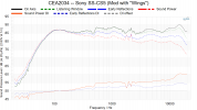
We must be working with very different Sony's. I plugged your crossover values into my design file, and the predicted response doesn't look like these measurements. My lspCad file predicts the stock response perfectly, and also predicts my mod accurately. But this is what I get with your values. It's always possible I made a mistake somewhere, although I've checked several times, but just looking at your woofer filter, reducing the value of the series inductor slightly to 1.0 mH with no change in the shunt cap value actually accentuates the baffle step problem on the stock unit. Just increasing the inductor value to 1.5 mH and eliminating the 2.2 Ohm resistor (which you also do) takes care of most of the sonic issuesJust put together the 3 way crossover with a few value tweaks. This looks, and sounds, good so far. I'm impressed at the $88/pair speaker. Basically a 90 degree listening window maybe? I'll flirting with a 2.5 way design too.
directivity 0,15,30,45 deg.
That 15 deg measurement in black looks great.

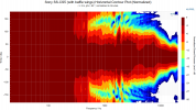
Separated for better visibility.
View attachment 188358
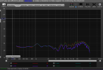
We must be working with very different Sony's. I plugged your crossover values into my design file, and the predicted response doesn't look like these measurements. My lspCad file predicts the stock response perfectly, and also predicts my mod accurately. But this is what I get with your values. It's always possible I made a mistake somewhere, although I've checked several times, but just looking at your woofer filter, reducing the value of the series inductor slightly to 1.0 mH with no change in the shunt cap value actually accentuates the baffle step problem on the stock unit. Just increasing the inductor value to 1.5 mH and eliminating the 2.2 Ohm resistor (which you also do) takes care of most of the sonic issues
with the stock Sony.
View attachment 189419
This is my predicted response for the stock Sony, which matches what others have measured:
View attachment 189420
I had to take some snips to the attachment points. Hot snot on the plastic catches that attaches the board to the cabinet were very annoying. I had a couple of whiskeys so I wasn't gentle lol. But yeah, I can see this being obnoxious for someone who is nervous about destroying their speakers.What's the problem with taking them apart? Danny Richie seemed to have no problem taking them apart.
Sony SS-CS5 Upgrade Kit | GR-Research
 www.audiosciencereview.com
What do you need?I have a pair of these by the way but have only taken input impedance measurements since I've
not yet opened them up. It would be interesting to get a model going in Xsim.
I usually cut my Praxis measurement plots off at 200 Hz when posting, because the response below that is very room dependent The Klippel measurements are much more reliable in this area. Praxis, which is superb measurement software otherwise, starts to transition from anechoic to room response a little above 200 Hz. So what you see below 200 Hz is highly room-dependent. If I moved the speakers to the opposite side of my measuring room, the deep bass response would be quite different. I've learned how to interpret these plots for a given location when I'm designing speakers, but they aren't intended to provide reliable bass response information for general use. However, above 200 Hz my plots have proven quite accurate and I've used them to design hundreds of speakers. I can't resolve the discrepancy between my measurements and predictions and those recorded by velocipede. All I can say with certainty is that a 1.0 mH inductor combined with a 10 uF shunt capacitor won't provide enough baffle step compensation to clear up the somewhat murky midrange that is the principal deficiency of the stock design.@Dennis Murphy How are you taking these measurements, near field in the bass?
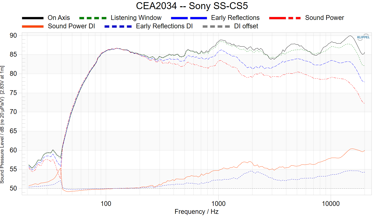
Here is Amir's thread, note that the on axis response (CEA2034) shows 100 Hz being
about equal to the output at 600 Hz whereas yours is more than 5 dB down:
https://www.audiosciencereview.com/forum/index.php?threads/sony-ss-cs5-3-way-speaker-review.13562/
Erin's CEA2034 on axis shows similar bass output:
Sony SS-CS5 bookshelf speaker (review by Erin)
Thanks to @hardisj for his review: https://www.erinsaudiocorner.com/loudspeakers/sony_sscs5/ Erin's conclusion: Let’s be real. This is a budget darling. I paid $88 for the pair. Most people are paying $130 or less. The performance is OK. It’s not going to knock your socks off with...
Yeah I'm not sure what is going on there. I have two calibrated mics. One from Minidsp and one from Dayton. I'm going to do some comparisons to see if there is a great disagreement between the two. I gate my measurements to remove reflections. How does your software deal with reflections?I usually cut my Praxis measurement plots off at 200 Hz when posting, because the response below that is very room dependent The Klippel measurements are much more reliable in this area. Praxis, which is superb measurement software otherwise, starts to transition from anechoic to room response a little above 200 Hz. So what you see below 200 Hz is highly room-dependent. If I moved the speakers to the opposite side of my measuring room, the deep bass response would be quite different. I've learned how to interpret these plots for a given location when I'm designing speakers, but they aren't intended to provide reliable bass response information for general use. However, above 200 Hz my plots have proven quite accurate and I've used them to design hundreds of speakers. I can't resolve the discrepancy between my measurements and predictions and those recorded by velocipede. All I can say with certainty is that a 1.0 mH inductor combined with a 10 uF shunt capacitor won't provide enough baffle step compensation to clear up the somewhat murky midrange that is the principal deficiency of the stock design.
It's a puzzler. I just sent in my Affordable Accuracy kit to Erin for a Klippel test, and it replicated my measurements as well, albeit with more resolution in the midrange. The one area where I don't think there's any room for disagreement is the bump at 1 kHz. I don't see how it's possible for your measurements to show no issue in this area when your mod doesn't do anything to address that bump.Yeah I'm not sure what is going on there. I have two calibrated mics. One from Minidsp and one from Dayton. I'm going to do some comparisons to see if there is a great disagreement between the two. I gate my measurements to remove reflections. How does your software deal with reflections?
Erin recently tested another speaker for me and provided me with a spinorama and it was quite close to what I tested with my mic I used on these speakers in the same settings and environment. So I don't know what's going on here. What I will do is change my testing setup to get a longer time gate to see if I can get more resolution and compare my two calibrated microphones. We'll see what happens. Hopefully I get congruent results.