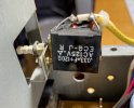
Hi all, I have a Denon DRA-300 and I believe it has a RC Snubber Circuit on the Power Switch. I am considering making one using the values ( .033uF + 120ohm ) printed on the side (see photo) to install on my recent refurbished Advent 350 to add some protection to the power switch. I have been doing research and get off into the weeds pretty fast trying to calculate the optimum RC snubber circuit. Need some practical advice, would the snubber circuit used on the Denon provide protection to my Advent power switch and for that matter work for most audio receiver. What are the down sides / risks. Thank you for any advice or insight you can provide me.

-
WANTED: Happy members who like to discuss audio and other topics related to our interest. Desire to learn and share knowledge of science required. There are many reviews of audio hardware and expert members to help answer your questions. Click here to have your audio equipment measured for free!
You are using an out of date browser. It may not display this or other websites correctly.
You should upgrade or use an alternative browser.
You should upgrade or use an alternative browser.
Snubber Circuits on the power switch? Pros and Cons
- Thread starter mteetank
- Start date
Don't get in the weeds. Just try it. Make sure the cap is sufficiently overrated.
It will have no impact on sound, it will just suppress the EMI (interference) from operating the switch and potentially lengthen the switch life by preventing arcs.
It will have no impact on sound, it will just suppress the EMI (interference) from operating the switch and potentially lengthen the switch life by preventing arcs.
- Thread Starter
- #3
So now for the design. I am going to use a .033uF Film Capacitor 250volts. From everything I have researched I still have no clue as to how to calculate resistor wattage. So if anyone can explain to me the recommended wattage for the 120 ohm resistor and the reasoning behind it I would be most appreciative. Thanks much!
AlfaNovember
Member
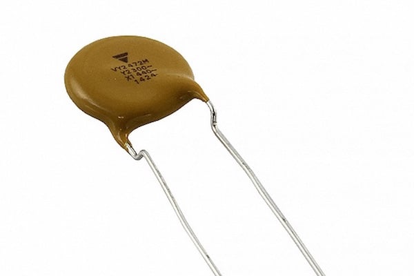
I am unqualified to speculate about the resistor wattage, but I would suggest using a Class X capacitor rated for across line use:
 www.allaboutcircuits.com
Safety Capacitors First: Class-X and Class-Y Capacitors - Technical Articles
Learn about Class-X and Class-Y capacitors, where they are used, and why they are referred to as
Resistor should be on the safe side with 2 Watt rating. Reason is that there is a very short time to prevent arcing thus the wattage is low. When the power switch is open then the current is small. Resistor can be carbon film or better metal film for long life. Some designs put only the capacitor without a resistor across the power switch. So at the Yamaha M-80 with .01uF which I repair right now.So now for the design. I am going to use a .033uF Film Capacitor 250volts. From everything I have researched I still have no clue as to how to calculate resistor wattage. So if anyone can explain to me the recommended wattage for the 120 ohm resistor and the reasoning behind it I would be most appreciative. Thanks much!
sam_adams
Major Contributor
- Joined
- Dec 24, 2019
- Messages
- 1,000
- Likes
- 2,435
Agree about a higher wattage resistor, especially to avoid exceeding the voltage rating.
- Thread Starter
- #8
I do like the idea of buying one already made. I also enjoy learning about what makes up the values.
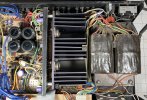
So now for installation. The Denon has it in series with the switch. In my internet travels, I have seen that some applications are across the switch (parallel) and in the Denon's case in line (series) to the switch. The one I will be install will be in my Advent 350 which has a very beefy transformer and over spec'd power capacitors.
So what are the pro's and cons of in series or in parallel on a audio receiver and if you were doing it, what would you choose? Thanks for taking the time!!!
Attachments
Exactly. The snubber goes as a series RC, but across the switch contacts. It most likely is to absorb transformer inductive kickback when the switch is opening.You do not want the resistor in series with the switch. It will drop voltage and get hot and burn up. Just use the cap on it's own.

Yes, to save the switch contacts. That's how I envisioned it being used (?)That Sounds like a plan! As per the diagram attached I am to use the "A" connection. Any thoughts on why Denon choose to hook it up as in "B".
Thanks much!
View attachment 287168
Use schema B ONLY as stated above. Use Class X capacitor as previously mentioned (or Class Y). Use at least a 0.5W non-carbon resistor, this is as much for the greater breakdown voltage due to the larger size as it is to do with power rating. 1W or 2 W are fine as well, but not 1/4W. Snubber goes across where the current break is to happen, it's to curb most arcing. I always buy snubbers so as to preserve my house insurance against claims...
Shouldn't matter. I'd put it on the neutral, just in case it does short (unlikely).To use the "B" circuit do you put the snubber on the neutral side or the hot side of the switch?
Good advice here. Or buy the packaged snubbers above.Use schema B ONLY as stated above. Use Class X capacitor as previously mentioned (or Class Y). Use at least a 0.5W non-carbon resistor, this is as much for the greater breakdown voltage due to the larger size as it is to do with power rating. 1W or 2 W are fine as well, but not 1/4W. Snubber goes across where the current break is to happen, it's to curb most arcing. I always buy snubbers so as to preserve my house insurance against claims...
This is a very unusual place to start learning electronics. Don't electrocute yourself or burn the house down.
/There, fair warning given
/There, fair warning given
Great! Just keep your face well away the first time you power itElectrocution is not in the plan! :>) I always unplug, check with a meter and then proceed. I really appreciate all the contributors to my post. I learned a lot and now am comfortable with how to proceed.
")
Similar threads
- Replies
- 0
- Views
- 244
- Replies
- 27
- Views
- 9K