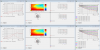
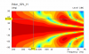
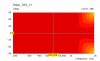
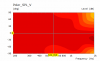
The simulation was done from 2k - 20 kHz. However, only visualization of wave propagation for the 20 kHz case was shown. I copied the plot of the differences between with screws and without screws here.


-
WANTED: Happy members who like to discuss audio and other topics related to our interest. Desire to learn and share knowledge of science required. There are many reviews of audio hardware and expert members to help answer your questions. Click here to have your audio equipment measured for free!
You are using an out of date browser. It may not display this or other websites correctly.
You should upgrade or use an alternative browser.
You should upgrade or use an alternative browser.
Simulation Analysis - Screws in Waveguide
- Thread starter René - Acculution.com
- Start date
OP
- Joined
- May 1, 2021
- Messages
- 427
- Likes
- 1,307
- Thread Starter
- #102
Thanks for your kind words, and the whole 'Dr' thing is not used much where I live when you have a PhD, so René is fine ;-)Dr. Rene, thank you very much for doing something very interesting and enlightening. You are making an extremely fine contribution to ASR, and I am very much looking forward to your findings with the other things you mentioned.
As you allude, it is quite apparent that with respect to acoustics especially, there is no other approach or method that compares to simulation. One of the members here, @ctrl, has done some very excellent work with his simulations, showing some of the effect of baffle edge diffraction and also waveguides. I expect that some of what you do will overlap with some of what he has done, and that there will be a positive synergistic effect. I look forward to this.
One thing I thought I would note in passing is that the frequency you used to assess the effect of the screw in the waveguide is high such that for many of us, it is moot because we can't hear it. Even when I was in my early thirties I could not hear above 15 kHz. I could only assume that I was able to hear 20 kHz at some younger age, but cannot say for certain. At this frequency, the wavelength is, I think, right about 1.7 cm, which means that the diameter of the little screw was slightly more that 1/3 of the wavelength. As such I am surprised that there was any effect at all, especially since it seems to me that the height of the screw is likely the more important dimension, and the height of the screw is less than 1/10 of the wavelength. Given that both dimensions, especially the height, are less than the wavelength by a significant amount, I expect that the effect of the screw will be nearly as great at 10 kHz as at 20 kHz. Obviously you cannot spend too much effort on the one question of the effect of the screw in the waveguide, but it would be interesting to see what the effect is at lower frequency (5 kHz would be good, for a tweeter frequency), and if the effect is still there at this frequency, to determine how much lower in height the screw will need to be in order for the effect to decrease to less than .1 dB, or if it is no longer significant at this frequency, to determine how much greater in height the screw needs to be in order for the effect to return to a level of significance. That said, it goes without saying that other people like me will take advantage of your kindness with this kind of question, "What happens if you change X a little bit, and then if you change Y a little bit, and heh, I'll wager that you change both X and Y together ..." There will be no end to this kind of thing, and you may find it practically necessary at some point to simply ignore these kinds of requests without so much as an acknowledgement!
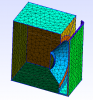
Yes, this can easily take up a lot of time, and the effects might not be audible (although it is visually disturbing with screws), and that is also a fine conclusion. Below I show how the sound field (real part of pressure visualized with contours also) is seemingly modified, here at 20 kHZ, whereas at 5 kHz I don't think there was much of an effect.
So it seems to modify the near-field so much that is shows up in the far-field, even if the wavelength is longer than the characteristic dimension; at least I don't see any mistakes in this quick analysis. I will do my best do answer questions as they come, but I might miss some.
The screws are present on the left, but they are 'made of air', so they do not disturb the field.
OP
- Joined
- May 1, 2021
- Messages
- 427
- Likes
- 1,307
- Thread Starter
- #103
Also, if there is any interest for a YouTube Q&A perhaps working through some simple examples, we could work something out.
Something weird seemed to happen to a couple of the posts I made where the images disappeared so I'm reposting them as the text makes very little sense without the images. The images were there when I quoted but not in the post as viewed, odd.For dome tweeters a basic circular arc seems to work pretty well and Ath has a nice function to be able to model the dome and surround as part of it's mesh generation which was added in later versions. That can stay axisymmetric or be modified around the outside to follow other functions and generate ellipses etc. The other main option uses Marcel's superformula to generate a closed form solution mating an OS throat to a Euler spiral / clothoid termination. Changing the parameters lets you go from pure OS to almost JMLC or anything in between.
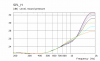
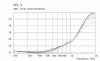
I am quite excited by the freestanding guides with rollback as in the BEM simulations I have run they seem to be much less affected by surrounding drivers or cabinets. I modelled the cone of a woofer in a box below the guide as a rigid boundary vs the same guide in free air and the difference was surprising. Top line is with woofer cabinet, bottom is without. A waveguide in a baffle with a woofer modelled as a rigid boundary in the baffle was much worse than either of these.
Attachments
Like this?
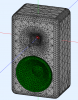
A single driver on it's own in an enclosure like this will act as bandpass chamber and put a peak in the response before dropping off.
If you array two or more of these drivers/enclosures that changes the radiation quite significantly narrowing the directivity based on the distance between the sources. This is what Genelec does in the Ones, narrowing the vertical but keeping the horizontal similar to the waveguide by using the racetrack shaped woofers.
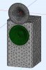
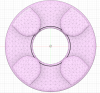
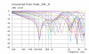
Here are the images of a slot loaded woofer similar to to how Genelec uses them, there is a bandpass response created with a large peak which is outside the passband and easy enough to equalize. The ring images show the effect of using four similar chambers in a ring formation which narrows the Horizontal and vertical directivity.
Attachments
-
 Ring Chamber.png343.8 KB · Views: 144
 -
 Sica Ring H Polar Curves.png21.8 KB · Views: 148
 -
 Sica Ring H Polar.png37.2 KB · Views: 122
 -
 Slot Chamber H Polar.png8.7 KB · Views: 115
 -
 Slot Chamber H SPL.png9.4 KB · Views: 126
 -
 Slot Chamber Mesh 2.png45.1 KB · Views: 121
 -
 Slot Chamber Mesh.png51.3 KB · Views: 127
 -
 Slot Chamber V Polar.png10 KB · Views: 117
 -
 Slot Chamber V SPL.png10.4 KB · Views: 121
Sigh. This is so true. I used to lecture at uni. Students will hit the eject button on a semester’s worth of knowledge as they walk out of the final exam.a major issue is that the average engineer has let go of a lot of knowledge acquired in uni
IMHO a huge problem is the disconnect between basics and current technology. Many engineers are all enthusiastic to keep abreast of the latest tools and technology, and become oblivious to the need to maintain skills in the underpinning fundamentals. Then they hit a wall when moving even slightly out of their comfort zone. They become little more than drones driving tools. It isn’t good.
OP
- Joined
- May 1, 2021
- Messages
- 427
- Likes
- 1,307
- Thread Starter
- #107
Nice. Which software is being used here?Here are the images of a slot loaded woofer similar to to how Genelec uses them, there is a bandpass response created with a large peak which is outside the passband and easy enough to equalize. The ring images show the effect of using four similar chambers in a ring formation which narrows the Horizontal and vertical directivity.
OP
- Joined
- May 1, 2021
- Messages
- 427
- Likes
- 1,307
- Thread Starter
- #108
Hi Francis. I probably work mostly with the upper tier students that have kind of the opposite problem, where they hope to get a job doing work like mine, but that is not how the industry works, and even if they manage to work highly scientifically they might be seen as outcasts. I cannot tell you how many times engineers(!) have asked me why I have open books on my desk...Sigh. This is so true. I used to lecture at uni. Students will hit the eject button on a semester’s worth of knowledge as they walk out of the final exam.
IMHO a huge problem is the disconnect between basics and current technology. Many engineers are all enthusiastic to keep abreast of the latest tools and technology, and become oblivious to the need to maintain skills in the underpinning fundamentals. Then they hit a wall when moving even slightly out of their comfort zone. They become little more than drones driving tools. It isn’t good.
The CAD drawings are made in Fusion 360, the meshes are generated in gmsh and the simulations (BEM) are in ABEC with the results being shown in VACS. All being free to use for non commercial purposes which is a bonus for meNice. Which software is being used here?
")
OP
- Joined
- May 1, 2021
- Messages
- 427
- Likes
- 1,307
- Thread Starter
- #110
Oh yeah, I think you mentioned that. I have met Joerg, and talk a lot with Lampos, and they made some fine software.The CAD drawings are made in Fusion 360, the meshes are generated in gmsh and the simulations (BEM) are in ABEC with the results being shown in VACS. All being free to use for non commercial purposes which is a bonus for me
maxxevv
Major Contributor
- Joined
- Apr 12, 2018
- Messages
- 1,872
- Likes
- 1,964
Hi Rene,
as previously mentioned, and as an overlap of the ASR Directiva project, attached are captures of what can be considered with DIY builds and what might be idealised in design of a simple speaker case.
They are Purifi PTT6.5X04-NFA-01 and SB Acoustics SB26ADC-C000-4 driver units.
Those 2 drivers are accurate models from CAD drawings and models provided by manufacturers.
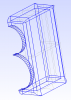
I have tried toplace the waveguide edges of the tweeter and woofer as level as within reason as shown in close up cross section.
They are all variations of one another, so its best that you pick what you believe to be worth the effort in simulating.

Various configurations.


The STEP214 model with all the different cases is too large to be attached here. (Due to the 2 drivers models being too large)
Let me know if I should mail it to you instead.
as previously mentioned, and as an overlap of the ASR Directiva project, attached are captures of what can be considered with DIY builds and what might be idealised in design of a simple speaker case.
They are Purifi PTT6.5X04-NFA-01 and SB Acoustics SB26ADC-C000-4 driver units.
Those 2 drivers are accurate models from CAD drawings and models provided by manufacturers.
I have tried toplace the waveguide edges of the tweeter and woofer as level as within reason as shown in close up cross section.
They are all variations of one another, so its best that you pick what you believe to be worth the effort in simulating.
Various configurations.
The STEP214 model with all the different cases is too large to be attached here. (Due to the 2 drivers models being too large)
Let me know if I should mail it to you instead.
OP
- Joined
- May 1, 2021
- Messages
- 427
- Likes
- 1,307
- Thread Starter
- #112
A lot of engineers were very interested in doing FEM, but when I said that there were a lot of basics they should study first, management shut me down, and now they try to learn via projects alone. So I left ;-)Sigh. This is so true. I used to lecture at uni. Students will hit the eject button on a semester’s worth of knowledge as they walk out of the final exam.
IMHO a huge problem is the disconnect between basics and current technology. Many engineers are all enthusiastic to keep abreast of the latest tools and technology, and become oblivious to the need to maintain skills in the underpinning fundamentals. Then they hit a wall when moving even slightly out of their comfort zone. They become little more than drones driving tools. It isn’t good.
OP
- Joined
- May 1, 2021
- Messages
- 427
- Likes
- 1,307
- Thread Starter
- #113
Thanks, it looks good. However, I want to investigate the effect of rounding edges first without any driver (flat piston(s) only) included, otherwise I jump too far into a specific project, and I don't have that much time or available computer power, and diffraction will be mixed with other effects and I want to look more qualitatively at this. I will soon post the results I have so far.Hi Rene,
as previously mentioned, and as an overlap of the ASR Directiva project, attached are captures of what can be considered with DIY builds and what might be idealised in design of a simple speaker case.
They are Purifi PTT6.5X04-NFA-01 and SB Acoustics SB26ADC-C000-4 driver units.
Those 2 drivers are accurate models from CAD drawings and models provided by manufacturers.
I have tried toplace the waveguide edges of the tweeter and woofer as level as within reason as shown in close up cross section.
They are all variations of one another, so its best that you pick what you believe to be worth the effort in simulating.
View attachment 128218
Various configurations.
View attachment 128219View attachment 128220View attachment 128221View attachment 128222View attachment 128223View attachment 128224View attachment 128225View attachment 128226View attachment 128227View attachment 128228View attachment 128229
The STEP214 model with all the different cases is too large to be attached here. (Due to the 2 drivers models being too large)
Let me know if I should mail it to you instead.
I am very grateful to Joerg for letting DIY enthusiasts use his software for free, so I try and show what I have been able to do with it where I can, in the hope that it benefits him somehow.Oh yeah, I think you mentioned that. I have met Joerg, and talk a lot with Lampos, and they made some fine software.
As to your baffle diffraction simulations, there is something with those you may be able to investigate and help me resolve. You have available a huge number of degrees of freedom and elements compared to the amount I can run in ABEC.
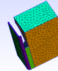
I have run simulations on two different types of corner rounding, a fully rounded corner and what I call mitre rounding, images attached to show what I mean. I have to use a lot of triangles to try and resolve the fully rounded corners and the results aren't quite what I expected and suspect may come down to mesh conformity which is better in the mitred case as gmsh turns it into more of a chamfer to look at.
Attachments
OP
- Joined
- May 1, 2021
- Messages
- 427
- Likes
- 1,307
- Thread Starter
- #115
How many elements per wavelenght do you have? And which order for the elements?I am very grateful to Joerg for letting DIY enthusiasts use his software for free, so I try and show what I have been able to do with it where I can, in the hope that it benefits him somehow.
As to your baffle diffraction simulations, there is something with those you may be able to investigate and help me resolve. You have available a huge number of degrees of freedom and elements compared to the amount I can run in ABEC.
I have run simulations on two different types of corner rounding, a fully rounded corner and what I call mitre rounding, images attached to show what I mean. I have to use a lot of triangles to try and resolve the fully rounded corners and the results aren't quite what I expected and suspect may come down to mesh conformity which is better in the mitred case as gmsh turns it into more of a chamfer to look at.
Quite so.A lot of engineers were very interested in doing FEM, but when I said that there were a lot of basics they should study first, management shut me down, and now they try to learn via projects alone. So I left ;-)
It is so important to start with the first principles because if you don't thoroughly understand them the project can veer well off course and it not be noticed or understood IME.
For fluid dynamics none of the FE code when I was working (I retired 11 years ago) could deal with unsteady flow. Most of the young engineers had never been in a wind tunnel with a bit of wool on a wand and just examined the flow field around a car (I worked on cars) so had no idea that the wheel flow is unsteady which meant that all their analyses gave wrong data downstream of the wheels without some sort of fudge factor.
The analyses were amazingly accurate for simple shapes like aircraft and for duct flow though.
In this case I have learned to drive the car but have a limited understanding of how it actually worksHow many elements per wavelenght do you have? And which order for the elements?
There is no mention of the order of the elements used in the ABEC documentation so I doubt that they are of any higher order.
In the mesh for the rounded corner cabinet above, the smallest element was 5mm (corners) and the largest 20mm (baffle flat face). I had to use half symmetry to capture the woofer and waveguide and that was the smallest I could reasonably go without the simulation running for an unreasonable length of time for me. When the number of elements gets above 5000 the time is usually more than 10 hours to solve. 10,000 seems to be the limit where the solution becomes impossible for ABEC to find at least within my lifetime.
OP
- Joined
- May 1, 2021
- Messages
- 427
- Likes
- 1,307
- Thread Starter
- #118
There is such a fine line between a simulation that is garbage and one that is sufficiently accurate, and that is why I often get send files from other companies in which they are 80-90 % there, but the results are all over the place. You simply need to understand the mathematics and the physics before you venture too much into solving multiphysics problem. This also creates this stigma that "simulations don't work" which is really annoying.Quite so.
It is so important to start with the first principles because if you don't thoroughly understand them the project can veer well off course and it not be noticed or understood IME.
For fluid dynamics none of the FE code when I was working (I retired 11 years ago) could deal with unsteady flow. Most of the young engineers had never been in a wind tunnel with a bit of wool on a wand and just examined the flow field around a car (I worked on cars) so had no idea that the wheel flow is unsteady which meant that all their analyses gave wrong data downstream of the wheels without some sort of fudge factor.
The analyses were amazingly accurate for simple shapes like aircraft and for duct flow though.
OP
- Joined
- May 1, 2021
- Messages
- 427
- Likes
- 1,307
- Thread Starter
- #119
Hmmm, 5 mm is okay up to 10 kHz. What makes you think that something is wrong, by the way?In this case I have learned to drive the car but have a limited understanding of how it actually works
There is no mention of the order of the elements used in the ABEC documentation so I doubt that they are of any higher order.
In the mesh for the rounded corner cabinet above, the smallest element was 5mm (corners) and the largest 20mm (baffle flat face). I had to use half symmetry to capture the woofer and waveguide and that was the smallest I could reasonably go without the simulation running for an unreasonable length of time for me. When the number of elements gets above 5000 the time is usually more than 10 hours to solve. 10,000 seems to be the limit where the solution becomes impossible for ABEC to find at least within my lifetime.
Some work has been done in that field, and shape optimization and waveguides are a great match. It can be done via polynomials or splines, or via more free form strategies. Some recent work has been done by Bezzola (https://www.researchgate.net/public...s_for_Acoustic_Elements_in_Loudspeaker_Design) and l looked at even more diverse cases (https://www.researchgate.net/public..._Topology_Optimization_of_Loudspeaker_Drivers).
I did some Work in that regard to, which is partially documented from here(Sorry it is in german, a blog in english is in development):
How-to-constant directivety-german
My investment starts from the linked post. The previus pages are quite interesting as well as Gaga did some studys about dome shapes ond offsets on waveguides. Translated with deepL the site should be readable.
The definition of a target and to make sure the results where smooth was my main obstacle during development as resonances dont change directivety and if thats your only criteria you get something awfully resonant. Calculation time is also an Issue. I iterate for x,y and then do the Impedance matching over Volume through the diagonal (volume gradient method if annyone wants to investigate further), so three planes are optimised which takes around 3 Days with 100 iterations each on a 1700x.
But as it seems I am getting left behind by other people who developed similar software and have a much firmer grasp at mathematics then I have and therefore develop better tools. Rene's observations regarding current engineers not knowing basics and beeing 80% there are all to true as I am one of those peaple sadly (see my enclosure studys) and my progress in fixing that runs at a crawling speed. But I DO know the value of an open book on a desk
Therefore I am deeply thankful for foks like Rene who take the time and energy to further better the understanding for such knowledge!
Similar threads
- Replies
- 5
- Views
- 576
- Replies
- 0
- Views
- 351
- Replies
- 2K
- Views
- 268K
- Replies
- 30
- Views
- 16K
- Poll
- Replies
- 362
- Views
- 50K