• WANTED: Happy members who like to discuss audio and other topics related to our interest. Desire to learn and share knowledge of science required. There are many reviews of audio hardware and expert members to help answer your questions. Click here to have your audio equipment measured for free!

Sigberg Audio Manta (12" wideband cardioid active speakers) development thread

Duke

Major Contributor
Audio Company
Forum Donor
Joined
Apr 22, 2016
Messages
1,557
Likes
3,864
Location
Princeton, Texas
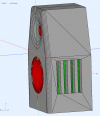
Possibly next design iteration on the baffle ports:
1656522910328.png


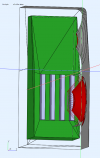
Testing in progress: :p


1656522945689.png

That's a really innovative way of dealing with the expanse of baffle to either side of your coaxial unit. I would guess that in addition to minimizing the baffle's effective size you are also minimizing the edge effects by partial attenuation, and by spreading those effects out across a much wider time interval, instead of them being concentrated in the time domain as is normally the case with a conventional baffle. My guess is that any residual baffle edge effects are therefore greatly weakened, which would improve not only the frequency response but ALSO (and perhaps more significantly) the image precision, something which does not show up in measurements.

And kudos on your effective cardioid loading, something easier said than done!! You probably had to develop your own "secret sauce(s)" by trial and error as I don't think there are any modelling programs which can handle the multiple complex interactions.

Kudos again on your imo brilliant decision to optimize for use with subwoofers rather than trying to juggle the inevitable tradeoffs involved in squeezing "adequate" bass out of the design. Same thing for your smaller speaker model - imo your global design decisions are very well thought-out.

I tip my virtual hat to you and your full-spectrum "outside the box" thinking.
 
Last edited:
OP
sigbergaudio

sigbergaudio

Major Contributor
Audio Company
Forum Donor
Joined
Aug 21, 2020
Messages
2,694
Likes
5,680
Location
Norway
I’m not a regular on ASR, but I do a lot of reading and I’ve gone through the entire Manta thread. Very cool looking and performing speaker! Thanks for sharing the process with us!

I’ve been trying to glean all I can about resistive, passive Cardioid speakers lately for my next planned build (non commercial). If you don’t mind, can you share if the response of the drivers shows a typical dipole peak and roll off at lower frequencies or does it simply act as an aperiodic enclosure with a corresponding impedance peak at resonance reduction? Do you have to boost the low end to account for any early roll off compared to the same size sealed enclosure?

And some unsolicited advice! I think they would look nicer if the felt in the front vents was more flush with the baffle, a bit slicker. Maybe with a convex mesh mounted from the inside. And even with the waveguide effects of the coax, you may be getting some diffraction, so It might also make your off axis measurements cleaner and follow the on axis even better. The sides look great as is to me.

Thanks!

Thank you for the feedback, highly appreciated!

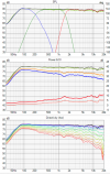
We haven't been at the Seas anechoic chamber with this particular prototype since there's already another iteration in the works with changes to the cabinet design. But here is the response of an earlier prototype. There's no EQ/correction of peaks in the low end here, actually there's a slight lift added at around 150hz if I remember correctly. But yes they obviously roll off early, also because the cabinet is far too small for proper bass response. Luckily that's intentional, as they're designed to play with subwoofers. So no boosting, actually the opposite has been applied; A high pass filter to allow maximum capacity while maintaining low excursion in the bottom end. :)

1643383056744-png.785659


With regards to the felt in the front vents: In the next iteration the slots on the front will be similar to the those on the side, and the felt will be recessed 50% less. Currently there's a pretty thick baffle. In the next iteration the baffle will be as thick as before in the lower chamber (for the 12"), but only half as thick for the coax (which doesn't need it), thus the baffle slots will be shallower. :)
 
OP
sigbergaudio

sigbergaudio

Major Contributor
Audio Company
Forum Donor
Joined
Aug 21, 2020
Messages
2,694
Likes
5,680
Location
Norway
That's a really innovative way of dealing with the expanse of baffle to either side of your coaxial unit. I would guess that in addition to minimizing the baffle's effective size you are also minimizing the edge effects by partial attenuation, and by spreading those effects out across a much wider time interval, instead of them being concentrated in the time domain as is normally the case with a conventional baffle. My guess is that any residual baffle edge effects are therefore greatly weakened, which would improve not only the frequency response but ALSO (and perhaps more significantly) the image precision, something which does not show up in measurements.

And kudos on your effective cardioid loading, something easier said than done!! You probably had to develop your own "secret sauce(s)" by trial and error as I don't think there are any modelling programs which can handle the multiple complex interactions.

Kudos again on your imo brilliant decision to optimize for use with subwoofers rather than trying to juggle the inevitable tradeoffs involved in squeezing "adequate" bass out of the design. Same thing for your smaller speaker model - imo your global design decisions are very well thought-out.

I tip my virtual hat to you and your full-spectrum "outside the box" thinking.

I highly appreciate the praise, especially coming from you @Duke, feedback like this makes all the work feel worthwile! :) (where's the heart emoji?)

Yes, this seem to be working very well, testing so far show minimal adverse diffraction effects on or off-axis. And it feels a bit weird to state that so confidently, but I've had so many people come by picking their jaw off the floor now that I'll just go out there and say it: The 3D effect / imaging of the current Manta prototype is simply beyond anything I've heard. The combination of the coax and the cardioid loading in such a wide band is exceptional. The full range sound aided by the subwoofer obviously also add to the sense of space.

And yes, the cardioid has taken a lot of trial and order, this project started November last year, so we're almost a year into it now. I hope to go into production next summer. :)
 
OP
sigbergaudio

sigbergaudio

Major Contributor
Audio Company
Forum Donor
Joined
Aug 21, 2020
Messages
2,694
Likes
5,680
Location
Norway
And even with the waveguide effects of the coax, you may be getting some diffraction, so It might also make your off axis measurements cleaner and follow the on axis even better.

Missed this part. I tested this, and there's no meaningful difference in diffraction effect when the foam in the slots is flush with the baffle compared to how it is now. But as mentioned in the previous comment they will be more shallow in the next iteration which will improve it visually. :)
 

Satx

Member
Joined
Aug 27, 2020
Messages
16
Likes
3
Thank you for the feedback, highly appreciated!

We haven't been at the Seas anechoic chamber with this particular prototype since there's already another iteration in the works with changes to the cabinet design. But here is the response of an earlier prototype. There's no EQ/correction of peaks in the low end here, actually there's a slight lift added at around 150hz if I remember correctly. But yes they obviously roll off early, also because the cabinet is far too small for proper bass response. Luckily that's intentional, as they're designed to play with subwoofers. So no boosting, actually the opposite has been applied; A high pass filter to allow maximum capacity while maintaining low excursion in the bottom end. :)

1643383056744-png.785659


With regards to the felt in the front vents: In the next iteration the slots on the front will be similar to the those on the side, and the felt will be recessed 50% less. Currently there's a pretty thick baffle. In the next iteration the baffle will be as thick as before in the lower chamber (for the 12"), but only half as thick for the coax (which doesn't need it), thus the baffle slots will be shallower. :)
So they do roll off earlier than, for instance, an infinite baffle response of the same driver? Before correction I mean. You said that a slight boost was added at 150hz and then also that a high pass was added because they extend too low, so I’m a little confused.

Also, if you don’t mind, did you find that the vents need to be a certain distance from the driver to provide the needed delay and did you find that the depth of the enclosure had an impact on the cardioid effect? And if so we’re you able to calculate these or is it just a matter of trial and error?

Thanks

This is from the “Everything you always wanted to know about cardioid thread”:

"204" is the on-axis measurement in front of the DUT, "202" is the bandwidth of interest, and "206, 208, 210" are measurements at 180 deg as a function of depth of inner panel: i.e. the depth behind the (cardioid) driver, internal to the enclosure. It is interesting to note that there is an optimum depth, "210", that lies between the closest back panel position (206) and the farthest position (208).

dd8c_patent_measurement.png
 
OP
sigbergaudio

sigbergaudio

Major Contributor
Audio Company
Forum Donor
Joined
Aug 21, 2020
Messages
2,694
Likes
5,680
Location
Norway
So they do roll off earlier than, for instance, an infinite baffle response of the same driver? Before correction I mean. You said that a slight boost was added at 150hz and then also that a high pass was added because they extend too low, so I’m a little confused.

I haven't simulated or tested this driver in an infinite baffle, but instinctively I wouldn't assume this design would roll off earlier than an IB.

I see how that can be confusing. I intentionally tune in a slight rise around 100-300hz (nothing to do with the cardioid, just how we tune our speakers, it's similar in the SBS.1). At the same time I don't want any extended output below 100hz (and especially below 50hz), thus the high pass filter.

Also, if you don’t mind, did you find that the vents need to be a certain distance from the driver to provide the needed delay and did you find that the depth of the enclosure had an impact on the cardioid effect? And if so we’re you able to calculate these or is it just a matter of trial and error?

Thanks

This is from the “Everything you always wanted to know about cardioid thread”:

"204" is the on-axis measurement in front of the DUT, "202" is the bandwidth of interest, and "206, 208, 210" are measurements at 180 deg as a function of depth of inner panel: i.e. the depth behind the (cardioid) driver, internal to the enclosure. It is interesting to note that there is an optimum depth, "210", that lies between the closest back panel position (206) and the farthest position (208).

dd8c_patent_measurement.png

I'm not prepared to disclose a lot of details with regards to this. But as Duke hinted at, this is pretty complicated stuff to calculate/simulate, so I can confirm that it is a lot of trial and error. :)
 

Satx

Member
Joined
Aug 27, 2020
Messages
16
Likes
3
I haven't simulated or tested this driver in an infinite baffle, but instinctively I wouldn't assume this design would roll off earlier than an IB.

I see how that can be confusing. I intentionally tune in a slight rise around 100-300hz (nothing to do with the cardioid, just how we tune our speakers, it's similar in the SBS.1). At the same time I don't want any extended output below 100hz (and especially below 50hz), thus the high pass filter.


I'm not prepared to disclose a lot of details with regards to this. But as Duke hinted at, this is pretty complicated stuff to calculate/simulate, so I can confirm that it is a lot of trial and error. :)
Ok, I got it on all points. You’ve invested the time, expense and effort on all that trial and error, so I don’t expect you to give up your secret recipe, so to speak! Since it did take a lot of trial and error, I’ll assume that those dimensions do in fact matter.

Thanks and good luck
 

ctrl

Major Contributor
Forum Donor
Joined
Jan 24, 2020
Messages
1,632
Likes
6,232
Location
.de, DE, DEU
Also, if you don’t mind, did you find that the vents need to be a certain distance from the driver to provide the needed delay and did you find that the depth of the enclosure had an impact on the cardioid effect? And if so we’re you able to calculate these or is it just a matter of trial and error?
Ok, I got it on all points. You’ve invested the time, expense and effort on all that trial and error, so I don’t expect you to give up your secret recipe, so to speak! Since it did take a lot of trial and error, I’ll assume that those dimensions do in fact matter.

It seems possible to simulate the slots with a BEM model using software (or comparable).
1663086265879.png 1663086279743.png
The simulation was also optimized with trail and error (and a little experience in LS design). As often in life, many things influence each other - baffle size, cabinet depth, slot size and position, slot number, slot distance, inner volume,...
Only that simulations were used, which is faster than building prototypes.
But since a simulation never reflects reality, there is always some uncertainty (compared to prototype builds) - at least until the first prototype based on the simulation is built.

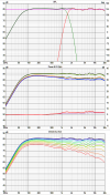
The simulations agree quite well with reality, at least in the case of the Directiva r2.
First measurement of prototype (+ bass modul) versus simulation (without bass extension):
1663086410956.png1663086429432.png
So it seems you can simulate speakers with slots if you don't mind the effort.
How reliable the simulations are in the end, however, will only become clear when different loudspeaker designs with slots have been simulated and the comparison to reality has been made.
 
OP
sigbergaudio

sigbergaudio

Major Contributor
Audio Company
Forum Donor
Joined
Aug 21, 2020
Messages
2,694
Likes
5,680
Location
Norway
The journey from idea to finished and commercialized loudspeaker isn't short and it isn't straight. It's more like crazy long and with quite a few unexpected turns. And there's a lot to do in addition to building the loudspeaker itself. You got to design and building packaging, user manuals, accessories, stands / brackets and whatnot..

Case in point: The last few months I've been pondering designs for loudspeaker stands to the Manta. We already have prototype stands, but the final stands probably won't look like those. An alternative design was created, and I finally got a finished prototype this weekend. They're made in 5mm powder coated steel. Extremely heavy and solid. I could probably punch a hole in a brick wall with them. And the stands themselves look great.

But visually they ended up looking too puny and thin compared to the pretty brutal look of the Manta. So this won't work. It could MAYBE work if the foot was significantly wider, and the column was twice was as wide (this is 50mm). But I'm starting to question the entire design with the single column in the middle. :oops: The bottom plate is suppoed to have feet below it too so that would add an illusion of thickness to the bottom plate, but still. Back to the drawing board..


1663516538214.png


--
 

BlackTalon

Addicted to Fun and Learning
Forum Donor
Joined
Apr 14, 2021
Messages
592
Likes
929
Location
DC
looks like a bodybuilder who doesn't believe in doing legs. Something that looks more massive would be a better aesthetic fit, even if the prototype stands are strong and stable enough. Maybe add so false columns at the corners.
 
OP
sigbergaudio

sigbergaudio

Major Contributor
Audio Company
Forum Donor
Joined
Aug 21, 2020
Messages
2,694
Likes
5,680
Location
Norway
@BlackTalon @Rednaxela Yes, the current prototypes (before the ones above) looks like that. The downside is that they're welded as one part, so they're not very shipping friendly. So not commercially viable as they are right now at least. Also, after adding the wooden detail at the bottom of the cabinet, this type of stands adds sort of a second line below the wood again. So would like a thinner top plate.

1651864160998-png.815253
 

ryanosaur

Major Contributor
Joined
Mar 17, 2022
Messages
1,550
Likes
2,490
Location
Cali
@BlackTalon @Rednaxela Yes, the current prototypes (before the ones above) looks like that. The downside is that they're welded as one part, so they're not very shipping friendly. So not commercially viable as they are right now at least. Also, after adding the wooden detail at the bottom of the cabinet, this type of stands adds sort of a second line below the wood again. So would like a thinner top plate.

1651864160998-png.815253
I sense a design competition!!!
Design a stand for our new Speaker and get a free pair of Mantas from the first production run!


Ya… I know… if wishes were wings…
;)
 

JustJones

Major Contributor
Forum Donor
Joined
Mar 31, 2020
Messages
1,745
Likes
2,462
Top plate size of speaker
4 hollow posts (round, square, rectangular)
Connect screw rods
Bottom plate little larger than top plate.
Not sure the weight of yours but my speakers are about 75lbs (34kg)
20220918_150232.jpg
 
OP
sigbergaudio

sigbergaudio

Major Contributor
Audio Company
Forum Donor
Joined
Aug 21, 2020
Messages
2,694
Likes
5,680
Location
Norway
Top plate size of speaker
4 hollow posts (round, square, rectangular)
Connect screw rods
Bottom plate little larger than top plate.
Not sure the weight of yours but my speakers are about 75lbs (34kg)

Yes, that is definitely a classic and well working design. It may end up something like that. Basically like the new prototype only it's four columns instead of one, and the bottom plate is solid.
 

Rednaxela

Major Contributor
Joined
Mar 30, 2022
Messages
2,108
Likes
2,739
Location
NL
Also, after adding the wooden detail at the bottom of the cabinet, this type of stands adds sort of a second line below the wood again. So would like a thinner top plate.
If you can make the top plate the same size as the speaker footprint, then visually it would become part of the speaker. I personally think that could work without having to make it thinner.

It’s just one data point and a very insignificant one, but in my humble opinion the four column solution takes a lot of elegance away compared to the picture in post 172.
 
OP
sigbergaudio

sigbergaudio

Major Contributor
Audio Company
Forum Donor
Joined
Aug 21, 2020
Messages
2,694
Likes
5,680
Location
Norway
If you can make the top plate the same size as the speaker footprint, then visually it would become part of the speaker. I personally think that could work without having to make it thinner.

It’s just one data point and a very insignificant one, but in my humble opinion the four column solution takes a lot of elegance away compared to the picture in post 172.

I appreciate the feedback. I will give it some thought. :)
 

Karu

Active Member
Forum Donor
Joined
Dec 23, 2019
Messages
220
Likes
200
Agree, isn’t there a solution where the thinner pillars/legs of post #171 can be bolted from top and bottom?
 

restorer-john

Grand Contributor
Joined
Mar 1, 2018
Messages
12,678
Likes
38,778
Location
Gold Coast, Queensland, Australia
I've got heaps of stands. I should photograph some of the ones that may suit your speaker. Like you say, a stand can make or break the aesthetic appeal of a speaker/stand combo.

Target from the UK made a fantastic range of stands over the years. Some of Jamo's stand were lovely, as were many of the Japanese home market Yamaha, Onkyo and Sony stands.
 

nc535

Member
Joined
Dec 30, 2021
Messages
52
Likes
62
that husky upper body almost begs to be a floor-stander. you should offer a high excursion 12" sub for it to sit on
 
Top Bottom