• WANTED: Happy members who like to discuss audio and other topics related to our interest. Desire to learn and share knowledge of science required. There are many reviews of audio hardware and expert members to help answer your questions. Click here to have your audio equipment measured for free!

SEAS Coaxial 3-Way Design Log

D!sco

Senior Member
Joined
Jun 16, 2021
Messages
498
Likes
399
h1699.jpg
h1456.jpg

This thread will serve as my log for iterations of this project. I am sharing it publicly for reference and constructive criticism. I am not a speaker design expert, or an audiophile guru. I'm some nerd with irregular, long bursts of free time and a rabbit hole. Building speaker kits was very rewarding for me. The value is high, and my satisfaction per dollar/hour has been fantastic building kits. This is not a project I intend to rush, or finish in a timely manner. Things will change, months or years will pass, and my goal is realistically to learn new things along the way. If a fabulous set of speakers is the result of all this effort, I'll be overwhelmed with joy. I've already taken a crack at a similar design with Tang Band 6.5" subs and coaxial drivers. The design wouldn't fit in my living room even if I gave up on my personal space.

The project goals are simple, but not easy. This is directly inspired by Directiva R1, but with a different approach. The purifi woofer is very attractive, but expensive for its SPL output. These will be pulling double duty as music/movie/party speakers. I expect these to work best paired with a sub. In order, the goals are:
1) Good directivity
The most important frequencies should be clearly audible in a large portion of the room for guests and unusual listening angles. I've chosen a coaxial for this reason. I don't just want good off-axis horizontal dispersion either, I want people to be able to sit and stand with equally decent listening ability.
2) Low distortion
I've had my share of crappy computer speakers and cheap hand-me-down vintage audio equipment. I'd like a build that is focused on it's composure. The plan is to stack multiple woofers for this reason, as it's my understanding that high excursion creates breakup and distortion. This may also help with the next goal,
3) High output
Since this will also take the role of mains during movies and TV, I'd like it to reach THX minimum standards, which I believe is 105dB. The stacked midbass should help with this if I go that route
4) Flat Response
I believe a flat response is important for listening to a variety of genres. Pretty sure no one here will argue with that. I like my bass rise to start a bit early at about 150-200Hz, and have +3 dB in the sub region if possible.
5) Reasonable size
Part of the reason 7" woofers were chosen is my limited space availability. I like their slim baffle format and I hope I don't need to build them out too deep.

The drivers in question:
SEAS MR18REX (Third-party FR and Distortion)
A midrange coaxial designed for 3-way applications. Loses output at 200hz. I have seen no designs using this coaxial, which worries me. The tweeter response is ragged in multiple measurements, including the manufacturers. Individuals praise it highly, but give no examples of it's use.
SEAS ER18RNX (Third-party FR and Distortion)
Decently well known midbass, used in the Zaph Audio SR71. Low distortion, high range, good output. It's an option. It's very aesthetically similar, and the frequency response is quite similar to the coax-mid. It's not a sub-bass power player, but it seems adequate for most purposes. I'm considering stacking two in parallel.
Scan-Speak Revelator 18W/4531G00
Instead of parallel midbass woofers, why not just go for a single, high quality quality driver in a large enclosure? Not my first choice but I'm keeping it in mind.

Some questions on the table:
Is the paper coaxial good enough?
The tweeter response can be quite ragged. It's also still best in class (available in the USA). That's not reassuring.
Should I go Hypex and sealed?
I'm not fixed on the current midbass, but I may be able to save space with a higher xmax/rms woofer controlled by DSP. My current box designs suggest a few options, but without distortion measurements below 200hz, I'm not sure how well these will play at high excursion.
Can I connect the coaxial woofer in parallel with the midbass?
The frequency responses are so similar that I'm wondering if I can just hook them up in a 2.5-way configuration. The mid-coax has a THD > 1% @ 250hz, so a first order transition between it and the midbass may help keep the midrange composed and therefore the waveguide for the tweeter composed. In the same vein, can the two be placed in a single, 14L enclosure instead of two 7L, or is that a bad idea? VCAD seems to have trouble simulating this, or I don't quite get how to use the enclosure tool.
Has anyone tried open-back or cardioid coaxials?
One of my first experiments with the coaxial may be putting it in a PVC pipe and seeing how it plays on a stand. We have the Statements to thank for this idea. I just hope this means I don't have to learn HornRESP.

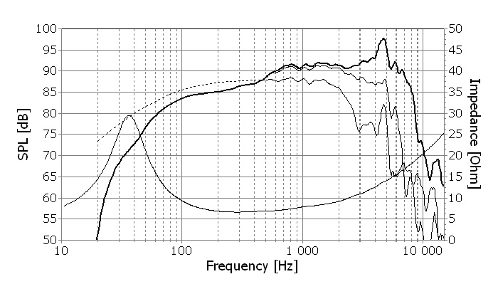
Anyways, here's the legwork, all done in VCAD with the SEAS provided FR/Impedances, on and off-axis. No baffle sim yet, no perfect half-space responses, but it's the minimum I'd do before taking a concept remotely seriously. I have four iterations, varying between three and four drivers, passive and active. They are currently simulating three enclosures in the FR:
A 7L sealed enclosure for the coaxial for an F3 ~200hz
A 7L sealed enclosure for the midwoofer when present for an F3 of ~100hz. Note that this sims better vertical directivity placed above the coaxial, in MCWW format.
A 28L ported enclosure with approximately two 76x250mm (3"x10") ports for the bass section. This does a good job limiting excursion up to 125W without ever touching the air velocity warning. VCAD estimates an f(b) of 55 at an output of 112dB. A single, shorter port can be used to reduce the f(b) to 40, while reducing the output to 105dB and the maximum current to ~80W, it's RMS power rating. The least likely design is a sealed 14L enclosure, restricting output to 50W/ch before hitting excursion limits at 100dB. Not very impressive on paper, and no room to EQ.
Screen Shot 2021-10-17 at 16.13.56.pngScreen Shot 2021-10-17 at 16.14.51.pngScreen Shot 2021-10-17 at 16.17.09.png
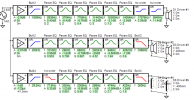
(Boxes tested with R1's passive crossover topology, ohms adjusted to reflect dual parallel woofers. PEQ and active crossovers have been adjusted to fit within enclosure spec)
SEAS 3-way Coaxial Tower Six-pack R1.pngSEAS 3-way Coaxial Tower XO-schema-1.png
SEAS 3-way Coaxial Tower Six-pack R2.pngSEAS 3-way Coaxial Tower XO-schema-2.png
SEAS 3-way Coaxial Tower Six-pack R3.pngSEAS 3-way Coaxial Tower XO-schema-3.png
SEAS 3-way Coaxial Tower Six-pack R4.pngSEAS 3-way Coaxial Tower XO-schema-4.png

Last, an enclosure mock-up:
Screen Shot 2021-10-17 at 16.02.30.png
Currently 1063mm (41") tall, 510mm (20") deep, and 200mm (~8") wide.
This is the CWW alignment. If I add the third ER18 woofer, the 7L sealed enclosure will probably go above the coaxial, in a MCWW alignment.
 
Last edited:
OP
D

D!sco

Senior Member
Joined
Jun 16, 2021
Messages
498
Likes
399
Spent some time this afternoon redesigning the enclosure for the MCWW variation. I managed to take 200mm off the depth and 50mm off the height. This is a substantial footprint reduction, very welcome in my living situation. They don't look big on-screen until they're ugly cardboard boxes in your house. Overall it should be a 44L enclosure with two 7L sealed boxes and a 28L enclosure I'll model ports for later. The new 12" depth should let them breathe in the room a bit better without shaking the walls. Alternatively, the max $$$ solution is SEAS passive radiators on the sides/rear.
SEAS Tower R3.png
 
OP
D

D!sco

Senior Member
Joined
Jun 16, 2021
Messages
498
Likes
399
I've had some free time lately, so I'm taking the baffle and enclosure design much more seriously now. I think the frequency response of a 20L-per-woofer bass reflex enclosure for the bass cabinet and a 7-9L sealed tube/cone for the coaxial would be ideal. If I actually build this, I could buy a pair of woofers, a coaxial, and pair of mockup cabinets to test their response in. The crazier R11 ripoff variant could easily be assembled by replicating the woofer box again and placing it on top of the coaxial, for two bass towers.

Simple mockup for the dual woofer enclosure:
Screen Shot 2021-12-14 at 12.33.46.pngScreen Shot 2021-12-14 at 12.43.43.pngSeas ER18RNX Six-pack.png
Woofers would be wired in parallel, internally. With two of the dual woofer enclosures, they would be wired to each other in series. Each box has a 10x20mm port (4x8"), calculated in the VCAD enclosure designer.

Simple mockup for the coaxial enclosure:
Screen Shot 2021-12-14 at 12.37.49.png
The coaxial box is the same width, but is much shorter. In a finalized version, this could allow woofer chambers to be joined, with a 75x200mm opening. I'll have to check if that would make noise.

Next issue has getting proper fullrange simulated responses out of this software. I'm not 100% sure of the order, though @headshake gave me a very helpful set of instructions on my Tang Band coaxial writeup. I'm still having the same issues as before, such as merging my half space responses with the driver responses and getting realistic responses from both the ports/enclosures and my drivers. When I settle on a box size, it's for multiple woofers. I'm not sure what to do with the half-space data in both the enclosure tool or the fullrange response tool. Am I supposed to merge them? I always get something funky like this for the woofers:

SEAS ER18RNX (H1456) Woofer 0deg mrg.png

It's clearly trying to merge the response of an 80L dual port enclosure with a single woofer. A 10dB jump would be funny if it wasn't so unbelievable. How can I effectively quarter the output of a pair of ports?? Going to step away for a bit, read some more tutorials, and see if the answer comes to me. If anyone can explain the order of operations that doesn't include spending $300 or more on drivers and measuring equipment right now, I'd love to hear it. All I have to work with for now is the factory measurements at 0, 30 and 60 degrees. Baffle diffraction tools should help calculate the rest, but am I ready to do that step, or should I be merging the enclosure with my FR before?
 
OP
D

D!sco

Senior Member
Joined
Jun 16, 2021
Messages
498
Likes
399
I finally got around to merging port simulations and doing baffle diffraction. It's surprising how much the correction resembles the SEAS "response with enclosure" line seen below:
H1456-curve.jpg


Definitely not a replacement for real measurements, but I can finally start working on directivity.

The KEF R11/R7 ripoff design has the best directivity, with -3dB at 45 degrees vertically. The crossover works for 2 or 4 woofers. 4 woofers allows bass boost and very high SPL, up to 117dB @ 50hz, vs 2 parallel woofers capping out at 110. Design goals are to have even vertical response, narrower than the horizontal response for less floor and ceiling bounce. The goal of making these coaxial is to reduce the need for perfect sitting positions, and allow people to stand and listen as well. Horizontal dispersion has been fantastic on all crossovers so far.
X-Over
1640634889784.png

Enclosure: (halve volume and number of ports for two woofer version)
Screen Shot 2021-12-27 at 12.20.28.png

1640636441991.png

1640635164457.png

1640635459335.png


Attempting to run the coaxial in a 2.5-way configuration with the midwoofer gave it an awful combing effect. It would have been nice to get a nominal 94dB sensitivity, but alas, placing a sealed mid above the coaxial has some disastrous consequences.
For the MCWW config:
1640635432248.png

And aligning the woofers in a configuration more like KEF's Q550 also led to a similar combing effect:
CWW(W)
1640636113312.png


This is all frustrating, as I was hoping the increased sensitivity would keep the coaxial woofer in better shape as a waveguide. Less excursion is better for distortion as both a midrange and the tweeter's waveguide. The directivity is also much better when the midrange crosses lower. Again, this is an excursion issue, and the reason for making it a 3.5-way in the first place. Letting long throw drivers handle the high excursion audio should keep the distortion very low overall.

I'm glad I figured out how to use the Response Optimizer. I can just run it 1000 times for preference score instead of fidgeting with crossover bits for eternity. What a relief.
 

Attachments

  • 1640635405868.png
    1640635405868.png
    41.2 KB · Views: 111
Last edited:
OP
D

D!sco

Senior Member
Joined
Jun 16, 2021
Messages
498
Likes
399
Yeah, driver prices are going up and stock speakers aren't. I ran some sims with super high order x-overs for fun. I might post them later, but currently I'm diverting my woodworking to improving DIY setups I already have. Rounding edges, improving baffle widths, etc. I want to turn my HiVi 3.1's into 4-way pyramids currently. Just need to pick the right 12" sub and, again, hope for deflation.
 
  • Like
Reactions: Zvu
OP
D

D!sco

Senior Member
Joined
Jun 16, 2021
Messages
498
Likes
399
I have been reading about how to create a cardioid effect with active subwoofers and I have applied it to this design. This adds another active channel to each speaker and two woofers facing the rear. It's far from perfect, but the gist is that the cardioid effect works at a specific frequency range depending on the woofer's operating range, the distance from the front woofers, and the delay applied. This interference is destructive, and reduces the volume of the forward facing woofers. To counter this, I'm using 4 woofers up front to prevent loss of maximum SPL. The midrange is still the weak link here, so levels and delays are set relative to it.
SEAS 3-way var8 XO-schema-8.png
SEAS 3-way var8 Six-pack.png


Non-Cardioid (left) vs Cardoid (right)
SEAS 3-way var4 Directivity (hor).png
SEAS 3-way var8 Directivity (hor).png

It's an expensive way to fix a minor problem, but it was fun to experiment with! Not sure how I would actually apply woofer crossovers. Maybe the best way would be to have an analog crossover for the coaxial and PEQ them through the upper channel.
 
OP
D

D!sco

Senior Member
Joined
Jun 16, 2021
Messages
498
Likes
399
Went a bit nuts on a hybrid design. Sacrifices phase for simplicity. This would allow a minidsp 4x8 to run two towers and a pair of subs. I let the optimizer work on the cardioid woofers for the fun of it, and it did a great job aligning phase for the best DI. This made it clear I either needed less cardioid woofers, or more front facing woofers. So I added a theoretical $400 in woofers to the design. Maybe I don't need to have such fancy woofers for a design that will use destrictive, positive interference? The Kii woofers are supposed to be quite cheap Peerless woofers.
SEAS 3-way var7 XO-schema-7.png
SEAS 3-way var7 Power+DI.png
SEAS 3-way var7 Directivity (hor).png
 
Top Bottom