
In a recent discussion, we were presented with a DAC built by a DIY hobbyist, turning businessman. I thought we take a look at this product and see why it is important to purchase equipment that is designed and engineered by professionals.
Block diagram and Functionality
Here is the DAC in question with my notations outlining the different components:

My focus here is mostly safety as this is a product that has mains input. Many DIY companies are smart enough to avoid many of the problems I will be outlining here by using external wall-wart supplies and hence the audio product itself, has no high voltage circuits. Those external supplies are (hopefully) designed by professional companies and are certified for safety and emissions. This DAC however, incorporates the AC power supply internally and with it, buys itself a heap of trouble.
Here is a more simplified block diagram of the DAC:

We have a socketed IEC mains input on top left. That is in turn wired to a noise/EMI filter made by Schaffner (FN9222ESB-15-06). The output of that goes into a "soft start" module made by Hypex. The idea of this product is to reduce the sudden peak current draw of the follow on power supply. It also has the added functionality of push-button power on/off.
The soft-start circuit in turn powers a commercial switchmode power supply. The version here is used without its protective metal cage. My guess is that this is the Daito Electron HFS-30.
The output of that supply goes to a regulator board which generates the different voltages needed for the DAC module and associated buffer/amplifier daughter card. The power regulators are mounted by the bottom heatsink. The top heat sink is unused.
The DAC board is hidden underneath so I can't make any comments about it. The buffer board seems to have discrete op-amp boards which themselves are socketed yet again (daughter card on top of daughter card).
The output of the buffers goes to balanced output XLR connectors using those socketed wire harnesses.
So at high level the device is pretty simple.
Design and Safety Concerns:
From the point of view of the uninitiated, the unit seems nice and tidy. Unfortunately once we dig into it from engineering point of view, a number of serious problems arise that you would not see from professional commercial products. Let's dig into those one by one:

1. Let's start from top right, the IEC mains input. Notice that push on connectors are used. Problem is, the connectors themselves are not insulated as you can see from their shiny looks. The exposed connectors mean that other wires may come in contact with them and get energized at full mains voltage. Such a wire for example may be the audio connector!
They can also come loose and touch adjacent conducting surfaces. Imagine for example if the green one that goes to the chassis comes loose and touches the hot conductor. Immediately the chassis of the entire unit gets energized with mains high voltage!!!
Would they ever come loose? Of course. I have bought equipment where they were dangling loose likely due to shock and vibration in shipping. I have also had them come loose on their own after while due heat expansion/contraction, vibrations (from music playing), etc.
How should it be done? Here is a random picture online that shows the minimum standard:

Notice the plastic shroud around the connector. If those connectors become disconnected, there is little of danger of them conducting to any other metal surface.
My own preference is actually have screw terminals with lock washers and such although admittedly, that is not the norm in residential products (but mandatory on boats where your life depends on it).
2. The next issue is the wiring of the Schaffner EMI noise filter. Lot of concerns and problems here.
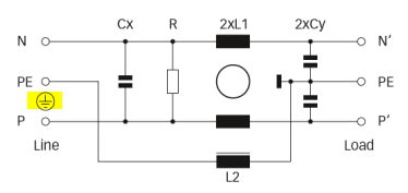
First, the input is not connected to chassis ground. Only the output of the filter is so connected. Let's look at the block diagram of this filter:

Left side is input (hot (p), Neutral (N) and PE (protective earth) ). Right side is the output.
In the DAC above, the PE connection is connected using green ground wire to the chassis. The input however, is not so terminated. It simply goes to the ground wire in the IEC mains.
Let's examine what happens if the hot (p) wire comes loose from the input and touches the chassis. The path of current would be to the output of the filter (PE on the right) which is connected to the chassis. It would then follow that to the input and eventually to the outlet and breaker box. That would put L2 in series with that current flow.
Schaffner does not document the L2 filter. Two things could happen depending on its make up. If L2 has low power capability (likely since ground does not carry current normally) then it will blow up inside the filter. Once there, the current flow stops and the chassis will remain at full voltage of the mains input!!! Touch the enclosure and you may be invited to a meeting with your ancestors in heaven!
The only safe condition would be if L2 is made up of very heavy wiring and hence, causes the breaker to pop.
The right solution would be to have the input PE connection tied down to the chassis. That would protect against hot wire anywhere touching the chassis as there is no path through an inductor as there is with the way the unit is wired.
2 (a). Performance issues.
As I explained the output of this filter goes through the soft-start circuit (ignore that for now) and powers the switchmode power supply. That power supply coming from reputable vendor means it already has its own filtering and certification for emissions. Here is its block diagram:

Looking at the yellow circled block to the left for now, we see that a properly designed noise and EMC filter is already in place. As such, there is no need for yet another external filter as deployed in this DAC and attending misadventures due to its wiring.
Oh, I forgot that a guy built this unit. As such, the saying of "if a little bit is good, a lot is better" applies. So why not put another filter in the path to AC? Wouldn't we want blacker backgrounds? Veils removed, etc? The enemy is noise and if one filter is good, two would be even better.
Well, no. First, a lot of filtering done here are high frequencies and well outside of audible noise. But importantly, we are actually introducing new problems with the second filter that would not be there otherwise!
Look at the right yellow circle now. We see a capacitor that goes to "A" which which connects to the ground wire. The ground wire goes to the main breaker panel and connects to neutral. What this is doing is shunting high frequency noise from output of the power supply to the input. While this reduces high frequency noise, it works in reverse and allows some of the mains current to flow forward into the output of the power supply.
Here is a more detailed diagram of this type of filtering:

Starting on the right, the "Y" capacitors marked by Cy1 and Cy2 perform this feedback, filtering function.
Something about that should look familiar to the added Schaffner filter in this DAC. Here it is again:
So right away we see duplication of functionality. But importantly we see that the add-on filter module is creating its own ground common mode current!!! In other words, by adding this filter externally, we made the problem of mains ground leakage worse. Since mains contributions are at 60 Hz and its harmonics, this is not something you want to do.
Furthermore, there are safety limits of how much ground leakage is allowed by code. Higher currents could risk shock to user given the high voltages involved. The amount allowed is in the order of 25 microamps or so -- pretty small values Doubling down there could very well exceed this limit.
But wait, we are not finished. Go back to the original wiring of this EMI filter. You see 5-6 inch wires connecting it to mains and from it to the power supply. These wires act as antennas at frequencies near cell phone frequencies (800 Mhz) as their length approaches the wavelength of those frequencies.
For any filter of this sort, it is essential to reduce the length of interconnects. This is why they make versions of this filter that attach directly to the mains IEC socket. That would eliminate the wiring and improve both safety and performance. And labor for that matter.
Better solution yet would be to eliminate this filter altogether. As noted, the power supply is fully certified and should be wired directly to mains using short wires. No doubt some subjective sighted test was done that led folks to think these filters have audible improvements. Well, I am super doubtful and at any rate, measurements should have been performed to see if there is a problem at all or if things have been made worse.
3. Soft-start. As noted, this is a circuit that gradually increases the current to the power supply. Seems like a good thing but it is not. It is only needed for devices with larger linear power supplies and their transformers. For a DAC, the power consumption is very low and at any rate, the power supply in question here is switchmode and has its own soft-start circuit!

Clearly this power supply is in need of no current limiting.
And it is not just me saying this, the designer of the soft-start module says it! https://www.hypex.nl/product/softstart-module/38#tab_downloads

A simple mechanical on-off switch should have been used instead of this module. It provides no needed functionality yet has more wiring in the path which can pick up noise. And can possibly cause oscillations/instability and failures in the switchmode power supply.
4. Lack of sufficient clearance. Notice this situation:

Look at where I have circled. That sharp metal is digging into what could be mains hot wire. With enough vibration with music and such, it could saw through it, and cause a short to chassis.
Then there is this:

The gray wire is mains and the navy wires are the audio signal output. Should a large surge voltage arrive it could very well jump between the mains wire onto the signal wire and make its way out of the unit.
Forgetting that, AC mains coupling could occur between those two sets of wires causing mains/hum leakage to the DAC output.
The whole floor planning of the unit is so poor. High voltage paths should not remotely be close to low-voltage/signal path. I will show examples of this later but this haphazard layout is recepie for both diminished performance and safety. Go back to my original block diagram and the physical layout should follow the same:
See how far the left side is from right side? In this DAC, they are a fraction of an inch from each other!
5. Post regulator.

Those regulators at the bottom need heat sinks to dissipate power they throw away to reduce the voltage to the target value. For heat to transfer, there needs to be a tight connection to a heatsink. This usually means screws through those holes or a retaining clip. I see none of that in there.
I also doubt that they need much of a heatsink. Small ones freestanding on the device would have been sufficient, allowing the large heatsinks to be removed from either side of the box (the top one is not used anyway). When was the last time you saw a DAC with heatsinks like this? This is an amplifier box, not DAC.
6. Poor choice of supply. Why on earth is this DAC using a switchmode power supply? Total power consumption of this DAC is very low. A clean, simple, linear power supply would have been the right solution.
Switchmode supplies are used to keep things small, cool, and light. None of that is required here.
7. Competing examples.
Let's quickly look at some DACs that are designed by proper engineers as opposed to DIY hobbyists. First up is the Benchmark DAC1:

Notice the use of linear regulator as indicated by the toroidal transformer. See the clean path of high voltage through the AC mains and its filter on the left, fully encapsulated in metal box. High voltage lines are all kept on the extreme left of the DAC and way separate from audio circuits on the right and back.
A single board is used for the entire functionality which eliminates wires, shortens the paths and allows for much more optimized solution. Notice how the audio connectors direct attach to the PC board instead of the long wires used by the DAC in question.
No massive heatsinks and the only regulator needing one is bolted to the bottom of the case (above the transformer).
It is an absolutely clean and professional unit, likely retailing for much less than the DIY DAC. And of course backed by measurements that confirm its proper design. And safety.
Here is the Mytek DAC:

Again, we see the use of linear power supply. The input filter is as I noted: directly at the mains IEC input. Connectors are sleeved to protect against shorts.
The regulators are in front with their freestanding black heatsinks. Single board again but with wiring to the connectors.
The difference is strikingly clear.
Summary:
DIY builds are becoming common these days. It is however one thing to build something for yourself but entirely different matter when you off such gear to consumers. Please be on guard with any such equipment that has AC mains input. If there are no safety certification (UL, CE, etc.) please avoid these devices. Yes, chances are low that you get killed but if you did, it would be too late to get your money back.
Even ignoring safety concerns, performance of these devices are highly in question seeing how they are sold without a single measurement of their output performance.
Block diagram and Functionality
Here is the DAC in question with my notations outlining the different components:
My focus here is mostly safety as this is a product that has mains input. Many DIY companies are smart enough to avoid many of the problems I will be outlining here by using external wall-wart supplies and hence the audio product itself, has no high voltage circuits. Those external supplies are (hopefully) designed by professional companies and are certified for safety and emissions. This DAC however, incorporates the AC power supply internally and with it, buys itself a heap of trouble.
Here is a more simplified block diagram of the DAC:
We have a socketed IEC mains input on top left. That is in turn wired to a noise/EMI filter made by Schaffner (FN9222ESB-15-06). The output of that goes into a "soft start" module made by Hypex. The idea of this product is to reduce the sudden peak current draw of the follow on power supply. It also has the added functionality of push-button power on/off.
The soft-start circuit in turn powers a commercial switchmode power supply. The version here is used without its protective metal cage. My guess is that this is the Daito Electron HFS-30.
The output of that supply goes to a regulator board which generates the different voltages needed for the DAC module and associated buffer/amplifier daughter card. The power regulators are mounted by the bottom heatsink. The top heat sink is unused.
The DAC board is hidden underneath so I can't make any comments about it. The buffer board seems to have discrete op-amp boards which themselves are socketed yet again (daughter card on top of daughter card).
The output of the buffers goes to balanced output XLR connectors using those socketed wire harnesses.
So at high level the device is pretty simple.
Design and Safety Concerns:
From the point of view of the uninitiated, the unit seems nice and tidy. Unfortunately once we dig into it from engineering point of view, a number of serious problems arise that you would not see from professional commercial products. Let's dig into those one by one:
1. Let's start from top right, the IEC mains input. Notice that push on connectors are used. Problem is, the connectors themselves are not insulated as you can see from their shiny looks. The exposed connectors mean that other wires may come in contact with them and get energized at full mains voltage. Such a wire for example may be the audio connector!
They can also come loose and touch adjacent conducting surfaces. Imagine for example if the green one that goes to the chassis comes loose and touches the hot conductor. Immediately the chassis of the entire unit gets energized with mains high voltage!!!
Would they ever come loose? Of course. I have bought equipment where they were dangling loose likely due to shock and vibration in shipping. I have also had them come loose on their own after while due heat expansion/contraction, vibrations (from music playing), etc.
How should it be done? Here is a random picture online that shows the minimum standard:
Notice the plastic shroud around the connector. If those connectors become disconnected, there is little of danger of them conducting to any other metal surface.
My own preference is actually have screw terminals with lock washers and such although admittedly, that is not the norm in residential products (but mandatory on boats where your life depends on it).
2. The next issue is the wiring of the Schaffner EMI noise filter. Lot of concerns and problems here.
First, the input is not connected to chassis ground. Only the output of the filter is so connected. Let's look at the block diagram of this filter:
Left side is input (hot (p), Neutral (N) and PE (protective earth) ). Right side is the output.
In the DAC above, the PE connection is connected using green ground wire to the chassis. The input however, is not so terminated. It simply goes to the ground wire in the IEC mains.
Let's examine what happens if the hot (p) wire comes loose from the input and touches the chassis. The path of current would be to the output of the filter (PE on the right) which is connected to the chassis. It would then follow that to the input and eventually to the outlet and breaker box. That would put L2 in series with that current flow.
Schaffner does not document the L2 filter. Two things could happen depending on its make up. If L2 has low power capability (likely since ground does not carry current normally) then it will blow up inside the filter. Once there, the current flow stops and the chassis will remain at full voltage of the mains input!!! Touch the enclosure and you may be invited to a meeting with your ancestors in heaven!
The only safe condition would be if L2 is made up of very heavy wiring and hence, causes the breaker to pop.
The right solution would be to have the input PE connection tied down to the chassis. That would protect against hot wire anywhere touching the chassis as there is no path through an inductor as there is with the way the unit is wired.
2 (a). Performance issues.
As I explained the output of this filter goes through the soft-start circuit (ignore that for now) and powers the switchmode power supply. That power supply coming from reputable vendor means it already has its own filtering and certification for emissions. Here is its block diagram:
Looking at the yellow circled block to the left for now, we see that a properly designed noise and EMC filter is already in place. As such, there is no need for yet another external filter as deployed in this DAC and attending misadventures due to its wiring.
Oh, I forgot that a guy built this unit. As such, the saying of "if a little bit is good, a lot is better" applies. So why not put another filter in the path to AC? Wouldn't we want blacker backgrounds? Veils removed, etc? The enemy is noise and if one filter is good, two would be even better.
Well, no. First, a lot of filtering done here are high frequencies and well outside of audible noise. But importantly, we are actually introducing new problems with the second filter that would not be there otherwise!
Look at the right yellow circle now. We see a capacitor that goes to "A" which which connects to the ground wire. The ground wire goes to the main breaker panel and connects to neutral. What this is doing is shunting high frequency noise from output of the power supply to the input. While this reduces high frequency noise, it works in reverse and allows some of the mains current to flow forward into the output of the power supply.
Here is a more detailed diagram of this type of filtering:
Starting on the right, the "Y" capacitors marked by Cy1 and Cy2 perform this feedback, filtering function.
Something about that should look familiar to the added Schaffner filter in this DAC. Here it is again:
So right away we see duplication of functionality. But importantly we see that the add-on filter module is creating its own ground common mode current!!! In other words, by adding this filter externally, we made the problem of mains ground leakage worse. Since mains contributions are at 60 Hz and its harmonics, this is not something you want to do.
Furthermore, there are safety limits of how much ground leakage is allowed by code. Higher currents could risk shock to user given the high voltages involved. The amount allowed is in the order of 25 microamps or so -- pretty small values Doubling down there could very well exceed this limit.
But wait, we are not finished. Go back to the original wiring of this EMI filter. You see 5-6 inch wires connecting it to mains and from it to the power supply. These wires act as antennas at frequencies near cell phone frequencies (800 Mhz) as their length approaches the wavelength of those frequencies.
For any filter of this sort, it is essential to reduce the length of interconnects. This is why they make versions of this filter that attach directly to the mains IEC socket. That would eliminate the wiring and improve both safety and performance. And labor for that matter.
Better solution yet would be to eliminate this filter altogether. As noted, the power supply is fully certified and should be wired directly to mains using short wires. No doubt some subjective sighted test was done that led folks to think these filters have audible improvements. Well, I am super doubtful and at any rate, measurements should have been performed to see if there is a problem at all or if things have been made worse.
3. Soft-start. As noted, this is a circuit that gradually increases the current to the power supply. Seems like a good thing but it is not. It is only needed for devices with larger linear power supplies and their transformers. For a DAC, the power consumption is very low and at any rate, the power supply in question here is switchmode and has its own soft-start circuit!
Clearly this power supply is in need of no current limiting.
And it is not just me saying this, the designer of the soft-start module says it! https://www.hypex.nl/product/softstart-module/38#tab_downloads
A simple mechanical on-off switch should have been used instead of this module. It provides no needed functionality yet has more wiring in the path which can pick up noise. And can possibly cause oscillations/instability and failures in the switchmode power supply.
4. Lack of sufficient clearance. Notice this situation:
Look at where I have circled. That sharp metal is digging into what could be mains hot wire. With enough vibration with music and such, it could saw through it, and cause a short to chassis.
Then there is this:
The gray wire is mains and the navy wires are the audio signal output. Should a large surge voltage arrive it could very well jump between the mains wire onto the signal wire and make its way out of the unit.
Forgetting that, AC mains coupling could occur between those two sets of wires causing mains/hum leakage to the DAC output.
The whole floor planning of the unit is so poor. High voltage paths should not remotely be close to low-voltage/signal path. I will show examples of this later but this haphazard layout is recepie for both diminished performance and safety. Go back to my original block diagram and the physical layout should follow the same:
See how far the left side is from right side? In this DAC, they are a fraction of an inch from each other!
5. Post regulator.
Those regulators at the bottom need heat sinks to dissipate power they throw away to reduce the voltage to the target value. For heat to transfer, there needs to be a tight connection to a heatsink. This usually means screws through those holes or a retaining clip. I see none of that in there.
I also doubt that they need much of a heatsink. Small ones freestanding on the device would have been sufficient, allowing the large heatsinks to be removed from either side of the box (the top one is not used anyway). When was the last time you saw a DAC with heatsinks like this? This is an amplifier box, not DAC.
6. Poor choice of supply. Why on earth is this DAC using a switchmode power supply? Total power consumption of this DAC is very low. A clean, simple, linear power supply would have been the right solution.
Switchmode supplies are used to keep things small, cool, and light. None of that is required here.
7. Competing examples.
Let's quickly look at some DACs that are designed by proper engineers as opposed to DIY hobbyists. First up is the Benchmark DAC1:
Notice the use of linear regulator as indicated by the toroidal transformer. See the clean path of high voltage through the AC mains and its filter on the left, fully encapsulated in metal box. High voltage lines are all kept on the extreme left of the DAC and way separate from audio circuits on the right and back.
A single board is used for the entire functionality which eliminates wires, shortens the paths and allows for much more optimized solution. Notice how the audio connectors direct attach to the PC board instead of the long wires used by the DAC in question.
No massive heatsinks and the only regulator needing one is bolted to the bottom of the case (above the transformer).
It is an absolutely clean and professional unit, likely retailing for much less than the DIY DAC. And of course backed by measurements that confirm its proper design. And safety.
Here is the Mytek DAC:
Again, we see the use of linear power supply. The input filter is as I noted: directly at the mains IEC input. Connectors are sleeved to protect against shorts.
The regulators are in front with their freestanding black heatsinks. Single board again but with wiring to the connectors.
The difference is strikingly clear.
Summary:
DIY builds are becoming common these days. It is however one thing to build something for yourself but entirely different matter when you off such gear to consumers. Please be on guard with any such equipment that has AC mains input. If there are no safety certification (UL, CE, etc.) please avoid these devices. Yes, chances are low that you get killed but if you did, it would be too late to get your money back
.Even ignoring safety concerns, performance of these devices are highly in question seeing how they are sold without a single measurement of their output performance.