I would also like to know the details of the internal processing steps, but they are not published. Even if it's a black box specification, I don't care if the actual processing is 44.1kHz because the sound quality and product quality are good.
I will try to lift the veil of secrecy a little in this matter.
Six years ago, when the mass production of amplifiers under the conditional name "Power-DAC" began, chip manufacturers were more honest with consumers and indicated specific figures in the technical documentation.
In "all-in-one" chips (digital inputs + modulator + output MOSFET) STA350BW and STA326 all input data is SRC'd to 96kHz and processed in the DAP at 96kHz. Then the PWM signal is fed from the modulator at a frequency of 384 kHz to the output MOSFET.
In more complex and powerful "Power-DAC", pairs of chips were used: a separate modulator and a separate amplifier with MOSFET-keys and a protection system.
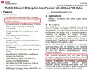
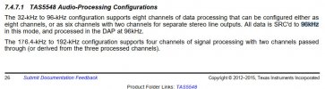
For example: TAS5548 and TAS5614LA. In the TAS5548 modulator, all signals with frequencies from 32-kHz to 96-kHz are also is SRC'd to 96kHz and processed in the DAP at 96kHz. And the 176.4-kHz to 192-kHz data was processed in native mode. But at the end, the 384-kHz PWM signal was fed to the TAS5614LA MOSFET-keys.
AXIGEN AX5689 has a sampling rate of the input signal: 32-768 kHz, 16 to 32-bit.
But the internal DSP processing still cannot exceed 192 kHz, because the CPU power will not be enough for high-quality operation of the tone block and LFE filter at a higher signal frequency in real-time mode.
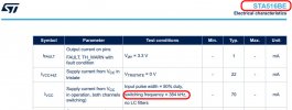
Moreover, the modulator AX5689 eventually outputs to the STA516BE all at the same PWM signal 384 kHz.
Just so as not to reduce sales, marketers should not advertise that a device receiving a 768 kHz signal will actually downsample it to 96 or 192 kHz.

")


.jpg")
.jpg")
.jpg")
.jpg")