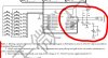
Some Chinese "engineers" save on flies. They don't even want to stick to the manufacturer's recommendations. Look at the following diagram. I put in the missing pieces and the situation improved. This is without shielding. I can't measure the noise right now. If someone does that and measures the noise, that would be great. And the copper screen is not needed. Thanks
I've used the TM1637 on an Arduino project I was working on.
The display manufacturer recommended a slightly different termination- 4.7k pull ups for the clock and data i/o pins, but no caps, but I did add some caps because of RF interference that it was generating.and slowing down the data and clock edges was recommended- as you noted.
Is this a similar situation? The vast majority of the noise is seemingly due to mains harmonic pick up.
Yes, the board is the same- without 100pF caps.
Have you actually measured the noise under the conditions that the review chose to evaluate?
Do you have spectral plots?