PDF attached. This is based on McFly's drawing, not my own build. Done in Fusion360, happy to send a design file if anyone wants it. Some notes:
This is above and beyond! I never expected this. I owe you a beer.
- Waveguide and Woofer cutouts in the baffle are extruded from the units actual 3d models. When I cut, I add a 1/2 mm or something on my CNC router (the Shaper Origin) so the drivers fit in more easily.
Agreed.
- I did not put port/binding post cutouts in the back because no specific model is called for or needed.
Agreed. Indeed binding posts/cups/terminals are designers choice
- Brace height is whatever you want but in this drawing it is at the edge of a small chamfer on the back of the woofer cutout.
Agreed. What I also should have mentioned (and I will try and remember to get in some photos) was the chamfer on the midbass cut out. I did quite a substantial one I think 15mm 45deg due to the thick baffle. One forgets to mention the things they do automatically when building speakers... heh
- You might consider raising drivers by 1-2mm so the gap at the bottom of the baffle matches the gap at the top. Here, it's 24mm on the bottom and almost 26 on the top.
110% - in fact I'd encourage it. It's what I was gunning for - 25mm top and 25mm bottom, however pinpoint precision with the waveguide routing was difficult for me, and these speakers were not built as final revisions. Moving the drivers 1 or 2mm will not hurt the crossover much at all.
- My speaker weighs 20lbs (9kg)
More perceived value in weight /s
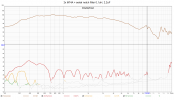
I just got home last night and finished one speaker this morning. The drivers seem to be playing their assigned range. Sounds quite good to me right now after very brief listening session with one unit. I'm pretty busy atm but will be able to do a basic couple of measurements to confirm it matches McFly's expectations. And will report back when I've listened more.
These are being shipped out to California, and I don't plan to install the woofers before that. Since I'm shipping anyway, I could send one to Amir on the way to CA if McFly approves and Amir/the community care enough. I understand he's buried in speakers though.
Excellent to hear you have the ability to measure. Please send me whatever result you get so we can peer review. I should be able to help if anything is odd, hopefully.
Re NFS scan - I been thinking about that a bit. I don't know if it's at the stage where it's worth putting through a NFS test just yet. Sure we could, and if it's okay, great! But if its not, it sorta tanks the project, and you gotta remember, I'm an amateur designer - see disclaimer in post 1. M105C never got the same level of scrutineering and design work that the Directiva got, or the same amount of widespread "peer-review", for lack of a better word, that other known established DIY designs have had.
Sure, if an NFS operator was willing to put in the time to measure each driver individually and send me the files so I could have another crack at the crossover (if required) thats also great. And if this were the case, I'd advocate for measuring with and without 25mm round overs if possible. Hell, even if they measured poorly just give us a chance to redo the crossover. Easy enough to do because its DIY and not commercial.
If we get a couple built and people are liking it and getting good results, lets revisit NFS. It's not that I don't have faith in my crossover work. I just don't have full faith in my mics - which means I don't get full faith in the finished crossover, especially when referenced against the gold standard NFS.
And I just wrecked my UMIK. So waiting for that replacement is slowing me down.


")