• WANTED: Happy members who like to discuss audio and other topics related to our interest. Desire to learn and share knowledge of science required. There are many reviews of audio hardware and expert members to help answer your questions. Click here to have your audio equipment measured for free!

RCA cable Magnetic interference measurement and comparison

Lambda

Major Contributor
Joined
Mar 22, 2020
Messages
1,791
Likes
1,525
Cables are cables and there is no difference?!

I designed a test to see if they perform significantly different in therms of "magnetic shielding" or Leakage inductance.
This test dose not test for ground loop currents but interference from close by magnetic in homogeneous magnetic files.

1636400154362.png

The basic setup looks like this but in my Case i use 47Ohms and not 1Mohm butt what ever the input impedance of the UMC404HD is
Absolute Vales are not important as we are making a relative comparison.

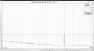
i turned the gain of the interface all the way up. so expect to see noise... then i made the extra effort to calibrate with a -50dBV source
cal-50dbV.png

In the Top right corner we measure -50.02dBV but if we look at the graph we only see about -65dB this is because of fft windowinng loss https://www.recordingblogs.com/wiki/scalloping-loss
So just add about 15dB to what you read in the graph or don’t since we anyways only comparing.

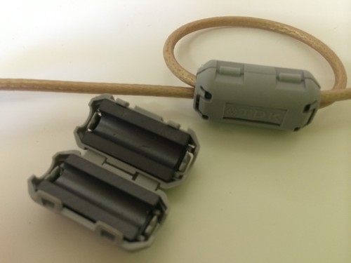
My first idea Was to just put the cable Close to switch mode power supply.
But my laptop Power supply seams to do spread spectrum and is very load dependent. so i tested a USB power supply with a LED lamp as fixed load

generic-usb-noise.png

Dayum the USB power supply at ~50Khz but i can clearly see it If i hold the cheap generic Cable close to it.
So the setup Seems to work...

Now we just need a better magnetic interference source in the audible spectrum with similar amplitude...
photo5210783383435720736.jpg


So i placed a Conventional transformer right on top of the Caleb under test.
And run the first round of tests with this Cables:
photo5210783383435720737.jpg

A "facy" Monster cabel "Xtra Low Noise DoubelHelical^tm Audio Cabel
Cheap but good looking Philips cable with big screen.
A rg174 coax ( I think ) with SMA to RCA adapters.
Cheap generic crap cable
And Telecom Twisted pair phone cable with foil shield.

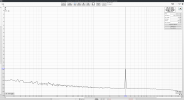
First the monster Cable under the transformer:
trafo-monster.png

50Hz and 150Hz at ruffly -115dBV (or -87,7dBV if we account for fft loss)

Now Nice looking Philips cable:
trafoPhilips.png

About the same little lower 50hz and 250hz peak

Now the RG-something Coax:
trafocoax.png

Well nothing... or At least nothing i can measure behind the background noise of my crapy audio interface.

Now it gets bad the nasty Generic cabel:
trafo-generic.png

150Hh at over -100dBV and some higher harmonics visible

Telecom Twisted pair with screen connected to one side (j9 or both sides(k):

tp-screen-om.png

tp-trafo-screenoff.png

So its about 5dB better with screen an About the same as -115dBV range as the other cables.

TL;DR
Generic ~ -84dBV @150Hz
Monster and Philips ~ -96dBV
Telecom Twisted pair with shield ~ -99dBV
RG Coax < -107dBV

Can you hear -84dBV?
Don’t know don't care and "it depends"

As i said multiple times this is all relative and the relative take away is.
A ideal cable can be >23dB better as a cray cable and and about 10dB Better Relative to a "monster" or Philips Cable

Do you need 10 to 23dB lower noise? Well if you don't hear any noise probably not!
 

Attachments

  • twistedpairwithscreen.png
    twistedpairwithscreen.png
    144.6 KB · Views: 112
  • twistedpairwithscreenon.png
    twistedpairwithscreenon.png
    143.8 KB · Views: 111
Last edited:
OP
L

Lambda

Major Contributor
Joined
Mar 22, 2020
Messages
1,791
Likes
1,525
Since the Transformer Results ware not Reproducible enough and there is lots of Noise at 50Hz and harmonics anyway i made a new test at 4kHz
since i have lower noise floor at 4Khz

To make it slightly more science i used a small 12V electric magnet and powered it with 2Vrms 4khz from my headphone output
magnet.jpg


Monster:
monster-85,7.png

-105dBV

Philips:
Philips-87,7.png

-124dBV

Generic:
generic-74,8.png

-90dBV

CoaxRG-something:
coax.png

-129dBV (had to increases the averaging to see it)

Twisted pair:
twistedpairwithscreenon.png

twistedpairwithscreen.png

Lets call it -104dBV

TL;DR
At 4khz and adding the fft loss we get
RG Coax -114dBV
Philips -109dBV
Monster -90dBV
Twisted pair -89dBV
And last place Generic -75dBV

At 4Khz the best is almost 40dB better as the generic Cable and the mosnter Cable is some how 19dB worse compered to the Philips Cable
 
Last edited:

Ordin Aryguy

Member
Joined
Feb 16, 2021
Messages
59
Likes
87
Location
Travelers Rest, SC
Seems like the real lesson here is to use a touch of common sense and not set transformers (or any other dramatic EM field generators) directly on top of your analog interface cables.

Here's another test for you. Take the cable that performed the worst in the above testing and measure its performance at increasing distances from the EM fields, something like 1" away, 2" away, etc. I believe you'll quickly find out that a little bit of distance makes a massive difference.
 

dougi

Addicted to Fun and Learning
Joined
May 31, 2020
Messages
845
Likes
765
Location
ACT, Australia
Yes I think rg6 like interconnects are good, both for shielding and for low capacitance. In most cases not very important though.

Below are noise plots of my phono preamp output, connected to the turntable via different cables/power supplies (not running).

Red is Kimber pbj (tri-twist), orange is the same but with a different PSU driving the phono amp, brown is a shielded cable.

1636405844229.png
 
OP
L

Lambda

Major Contributor
Joined
Mar 22, 2020
Messages
1,791
Likes
1,525
Here's another test for you. Take the cable that performed the worst in the above testing and measure its performance at increasing distances from the EM fields, something like 1" away, 2" away, etc. I believe you'll quickly find out that a little bit of distance makes a massive difference.
You don’t seem to get the takeaway from the test...
This is a Relative Comparison with an unknown field strength. The the fields are just kept constant as good as possible and therefore it dose not matter.

The Take a way here is Better cables give you up to ~40dB less noise (all else being equal).
If you don’t have or here any noise this is not relevant to you!
But if you have Noise issues keep in mind Cables Can make a Difference of up to 40dB (more realistically 20dB if you don't start with crap cables)

Are there other ways to get rid of interference? Sure but this aint about this.

Yes I think rg6 like interconnects are good, both for shielding and for low capacitance.
I think i used RG175 and i would not sugest it for Phono use because it has relatively high capacitance ( i think)
 

restorer-john

Grand Contributor
Joined
Mar 1, 2018
Messages
12,703
Likes
38,849
Location
Gold Coast, Queensland, Australia
Good thought to take the twisted pair/coax discussion into another thread. :)

My first comment concerns all the cables being different lengths, with the RF coax getting a huge advantage being so short.

I'd like to see them all the same length, terminated and placed identically. I was also considering doing something similar myself.
 

Ordin Aryguy

Member
Joined
Feb 16, 2021
Messages
59
Likes
87
Location
Travelers Rest, SC
You don’t seem to get the takeaway from the test...
This is a Relative Comparison with an unknown field strength. The the fields are just kept constant as good as possible and therefore it dose not matter.

The Take a way here is Better cables give you up to ~40dB less noise (all else being equal).
If you don’t have or here any noise this is not relevant to you!
But if you have Noise issues keep in mind Cables Can make a Difference of up to 40dB (more realistically 20dB if you don't start with crap cables)

Are there other ways to get rid of interference? Sure but this aint about this.


I think i used RG175 and i would not sugest it for Phono use because it has relatively high capacitance ( i think)

Please run the test I suggested. Distance vs. measured "noise" impinged on the cables.

I my world (EE, lots of EMC experience) distance is your friend. If there is something that is an EM generator, keep it the hell away from sensitive circuitry. Distance is free and distance is effective. If distance from EM fields isn't possible, then start spending money on shielding, etc.
 
OP
L

Lambda

Major Contributor
Joined
Mar 22, 2020
Messages
1,791
Likes
1,525
distance is your friend.
I know. distance is very critical! especially if the source is small.
You are right!
But this is outside the scope of this test.
This test has enough variables and unknowns and i’m only comparing one type of cable to an other in a "worst case" scenario.
 
OP
L

Lambda

Major Contributor
Joined
Mar 22, 2020
Messages
1,791
Likes
1,525
My first comment concerns all the cables being different lengths, with the RF coax getting a huge advantage being so short.
Good point. You are right kind of right there....
But it makes no practical difference since the magnetic filed is only Applied at a very small area and there is no Common mode current on the cable
And as @Ordin Aryguy says distance is verry critical

I'd like to see them all the same length, terminated and placed identically. I was also considering doing something similar myself.
The termination is shown in the first picture. Only one side is connected to Earth ground.
So it makes no practical difference in this test/case

In fact you see the Coax is female-female RCA and i used the Philips cabel at one side and the Monster Cabel on the oter side as extension/ gender changer so i can plug in my female RCA Resistor terminator
 
OP
L

Lambda

Major Contributor
Joined
Mar 22, 2020
Messages
1,791
Likes
1,525
The Last test was magnetic interference alone and Length Independent.

An other Common source of Noise is Common mode currents.(from ground loops or for example)
To test this I applied 100mV over a 10Ohm resistor (so around 10mA) to the Caleb Screen the other side ground an i measure the output.
the lower the Cable resistance the lower the output.

-19dBV=0dBFS
common mode current.png

worst cable -55dBV
Best cable -67dBV

This test is not Length independent and i used cables between 1.5 and 2m length. So i don’t bother to label them since this is not a fair comparison but a "prov of concept".

What Common mode Voltage and impedance or Current should i test with?

What's the maximum allowed (Common mode voltage) on a USB port for example?
The Loop loop impedance: Mains Ground -->PC-->USB-->DAC-->RCA-->AMP-->Mains ground?

The take away here is if you have hum or buzz from a Ground loop between tow class 1 devices the choice of Cable typ, and length alone makes Easily >12dB difference.
 
OP
L

Lambda

Major Contributor
Joined
Mar 22, 2020
Messages
1,791
Likes
1,525
If many class 1 Devices share the same ground but are spaced apart and maybe plugged in different outlets there is often (inevitably) a small potential difference between them

Example: An AVR connects to Antenna Ground, a class 1 video Projector on different outed, a TV(class 1), PC (class1)...
All this devices share more or less the same ground but then can be a view mV potential between them.
You can easily check this by touching the metal case of a Class 1 device with the tip from a RCA cable going in an amplifier or Audio interface.
Likely there is gonna be some buzz although it’s grounded.
And not only 50/60Hz! switch mode power supply put lots noise on the Ground and especially thinks that are Ground Referenced over USB (like DACs) often have Higher pitch buzz in wining tones on there ground.
With PCs its not uncommon to "hear" noise correlated to CPU and GPU activity.
I don’t want to go in detiele in how this is here an now.
But Its very real and many user have head this problem.

"Use Balanced" is the obvious answer to this. And that right. But can a "better" RCA make a difference?
Yes it can.

In this test i inject a small voltage ~2,2mV or -53dBV inductively into the cable.
I calibrated this with a secondary sense winding to ensure i have a flat frequency response and always the same voltage.
Loop impedance is basically only the cable impedance.

1636676425184.png


At low frequency the noise is basically equal to the injection voltage.
But a higher frequency there is a lot of difference
at 1Khz it is already 10dB and up to 25dB 20khz.

What makes this difference?!
In this case 2 ferrites installed like this on the Generic cabel make this difference
$_12.JPG
1636676885882.png


Seven Ferrites on the Philips Cabel:
1636677265495.png

7 ferrite clamp may sound excessive and it is but keep in mind they cost like 20cent each.
it looked a bit silly like this:
dmrm79kttx211.jpg

(Source internet)

TL;DR
If low impedance Common mode (ground loop) Noise is the Problem, Ferrites and "good cabel" make a difference.
Not only for HF and RF but also about 10dB at 1Khz.
(your mileage may vary).
 

fineMen

Major Contributor
Joined
Oct 31, 2021
Messages
1,504
Likes
680
If many class 1 Devices share the same ground but are spaced apart and maybe plugged in different outlets there is often (inevitably) a small potential difference between them

(your mileage may vary).
Yo, You're right. Thank's a lot for Your effort to explain. It was a little bit too much, I have to say. Honestly and frankly, the circuit could have shown the effect with two thirds removed at one glance. ( I overdo myself all the time ... ;-)

So, the easy pleasy way to desaster is not just the common protective ground, but that the signal lines share it. Ground loop! Of course and under all circumstances, if there is protective ground, use it. Remove it, and You'll find Yourselves in AudioPhools Heaven, if there is an afterlife. All trumpets and harps Dolby Celestial in I don't know how many dimensions there are.

I've got no clue how critical medical equipment is expected to do things, though. Please rapidly forget all my comments before.

I' m under the strong impression, that a connection of audio signal ground to protective ground shouldn't exsist. But, if there is a connection the beads should provide a much stronger induction, because the main distraction would be mains hum, including odd harmonics?
 

Jinjuku

Major Contributor
Forum Donor
Joined
Feb 28, 2016
Messages
1,279
Likes
1,180
RANE has had an engineering note posted for what seems like forever on CMNR and SE cabling, how they are/can be constructed, and best practices.

Coaxial (RG59/6) is affordable and represents even loading for SE applications. We use that for SDI 4:4:4 at 1080p30 up to 70 meters.

For other applications CMNR it is.

Another good paper is Siemons 'The antenna myth'. Thank goodness you can get highly performing cables for not a lot of money.
 
Last edited:

Cbdb2

Major Contributor
Joined
Sep 8, 2019
Messages
1,553
Likes
1,534
Location
Vancouver
You don’t seem to get the takeaway from the test...
This is a Relative Comparison with an unknown field strength. The the fields are just kept constant as good as possible and therefore it dose not matter.

The Take a way here is Better cables give you up to ~40dB less noise (all else being equal).
If you don’t have or here any noise this is not relevant to you!
But if you have Noise issues keep in mind Cables Can make a Difference of up to 40dB (more realistically 20dB if you don't start with crap cables)

Are there other ways to get rid of interference? Sure but this aint about this.


I think i used RG175 and i would not sugest it for Phono use because it has relatively high capacitance ( i think)
What he might be saying is that your so close to the field that orientation might make a difference. In a loose twisted pair if one conductor is as close to the magnet and the other is as far as possible you might get different results than both conducters the same distance. The conductors in the first case will be in different field strengths. A coax should not matter.
 

Bacek

New Member
Joined
Nov 23, 2022
Messages
4
Likes
1
Great thread. I'm realy curious how would work G vs I vs J vs K on same cable but with configurations as on pictures (ex. some microphone one). Actualy I don't fully understand who to make left side of J. Where ground should be connected? To some metal case around resistor (similar to turntable ground)?
 

Speedskater

Major Contributor
Joined
Mar 5, 2016
Messages
1,641
Likes
1,362
Location
Cleveland, Ohio USA

ku1185

Member
Joined
Jan 29, 2021
Messages
10
Likes
2
If many class 1 Devices share the same ground but are spaced apart and maybe plugged in different outlets there is often (inevitably) a small potential difference between them

Example: An AVR connects to Antenna Ground, a class 1 video Projector on different outed, a TV(class 1), PC (class1)...
All this devices share more or less the same ground but then can be a view mV potential between them.
You can easily check this by touching the metal case of a Class 1 device with the tip from a RCA cable going in an amplifier or Audio interface.
Likely there is gonna be some buzz although it’s grounded.
And not only 50/60Hz! switch mode power supply put lots noise on the Ground and especially thinks that are Ground Referenced over USB (like DACs) often have Higher pitch buzz in wining tones on there ground.
With PCs its not uncommon to "hear" noise correlated to CPU and GPU activity.
I don’t want to go in detiele in how this is here an now.
But Its very real and many user have head this problem.

"Use Balanced" is the obvious answer to this. And that right. But can a "better" RCA make a difference?
Yes it can.

In this test i inject a small voltage ~2,2mV or -53dBV inductively into the cable.
I calibrated this with a secondary sense winding to ensure i have a flat frequency response and always the same voltage.
Loop impedance is basically only the cable impedance.

View attachment 164813

At low frequency the noise is basically equal to the injection voltage.
But a higher frequency there is a lot of difference
at 1Khz it is already 10dB and up to 25dB 20khz.

What makes this difference?!
In this case 2 ferrites installed like this on the Generic cabel make this difference
$_12.JPG
View attachment 164814

Seven Ferrites on the Philips Cabel:
View attachment 164815
7 ferrite clamp may sound excessive and it is but keep in mind they cost like 20cent each.
it looked a bit silly like this:
dmrm79kttx211.jpg

(Source internet)

TL;DR
If low impedance Common mode (ground loop) Noise is the Problem, Ferrites and "good cabel" make a difference.
Not only for HF and RF but also about 10dB at 1Khz.
(your mileage may vary).
Sorry to revive an old thread. This was very informative.

About the ferrites, do you know how much different "mixes" make? Using just random cheap ferrite clamps, I've been able to address some noise issues caused by a device that I cannot (or really, should not) disconnect. I'm wondering if particular mix--specifically, mix 31 seems to come up a lot-- could prove useful.
 
Top Bottom