• WANTED: Happy members who like to discuss audio and other topics related to our interest. Desire to learn and share knowledge of science required. There are many reviews of audio hardware and expert members to help answer your questions. Click here to have your audio equipment measured for free!

Quick measurements of Forte 1a, a 50wpc class A amp by Nelson Pass

pkane

Master Contributor
Forum Donor
Joined
Aug 18, 2017
Messages
5,698
Likes
10,375
Location
North-East
Nelson updated Forte with more of the audiophile tweaks in later versions. 1a, while operating in pure class A mode, has a significant amount of negative feedback compared to its younger siblings. I had the amp on the bench to try to measure ultrasonic and RF interference from DACs into the amp, and since it was already hooked up, decided to take some quick measurements. All measurements were made at 1w into 8Ω.


PLEASE NOTE: An updated set of measurements with better power isolation, bias adjustment, and a different DAC were performed here (link). This resulted is a much better set of amp measurements. Some of the original measurements were updated in this post.

1kHz and harmonic distortion measurement using REW and Apogee Element24 as ADC @ 192kHz:
index.php


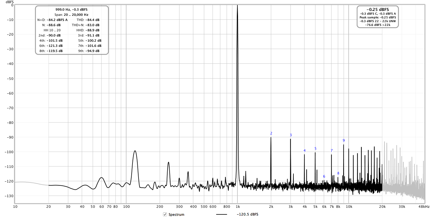
I couldn't find a way to get rid of the 120Hz frequency.

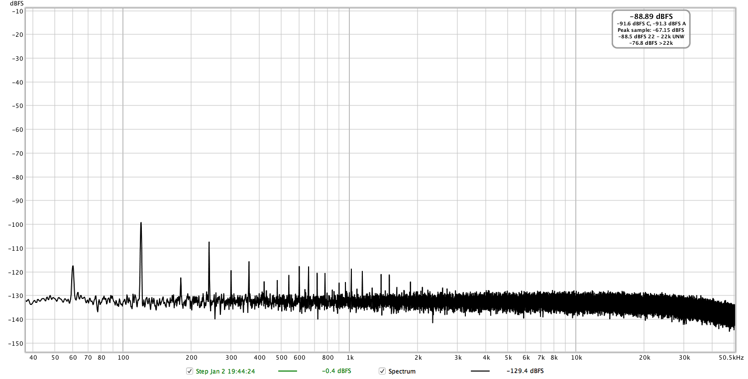
Here's no signal going into the amp, but the amp is on (nearly the same as amp being off!)
index.php


Frequency response is pretty good, about 4dB down at 40kHz, 3dB down at 10Hz:
fr-48k.png


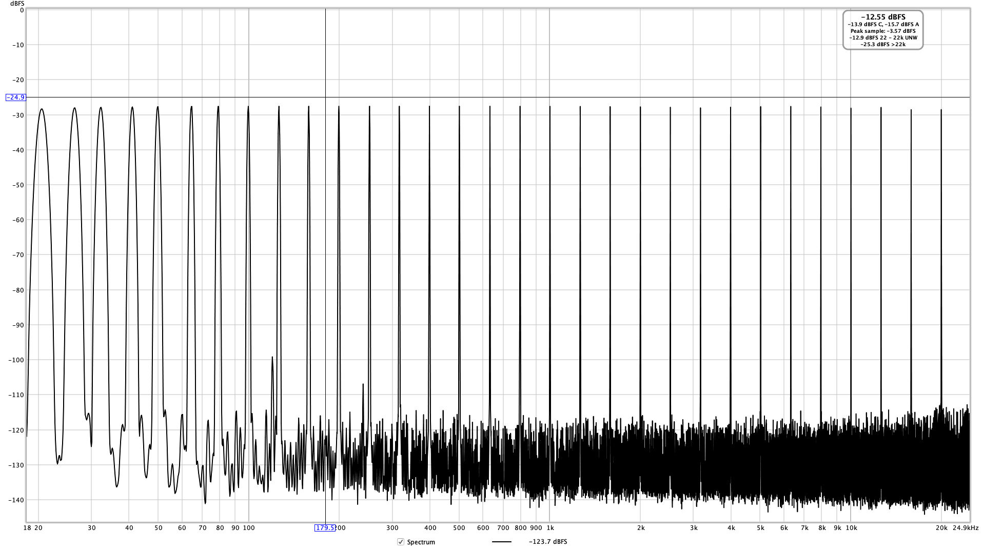
Multi-tone test shows increased noise due to IMD towards higher frequencies:
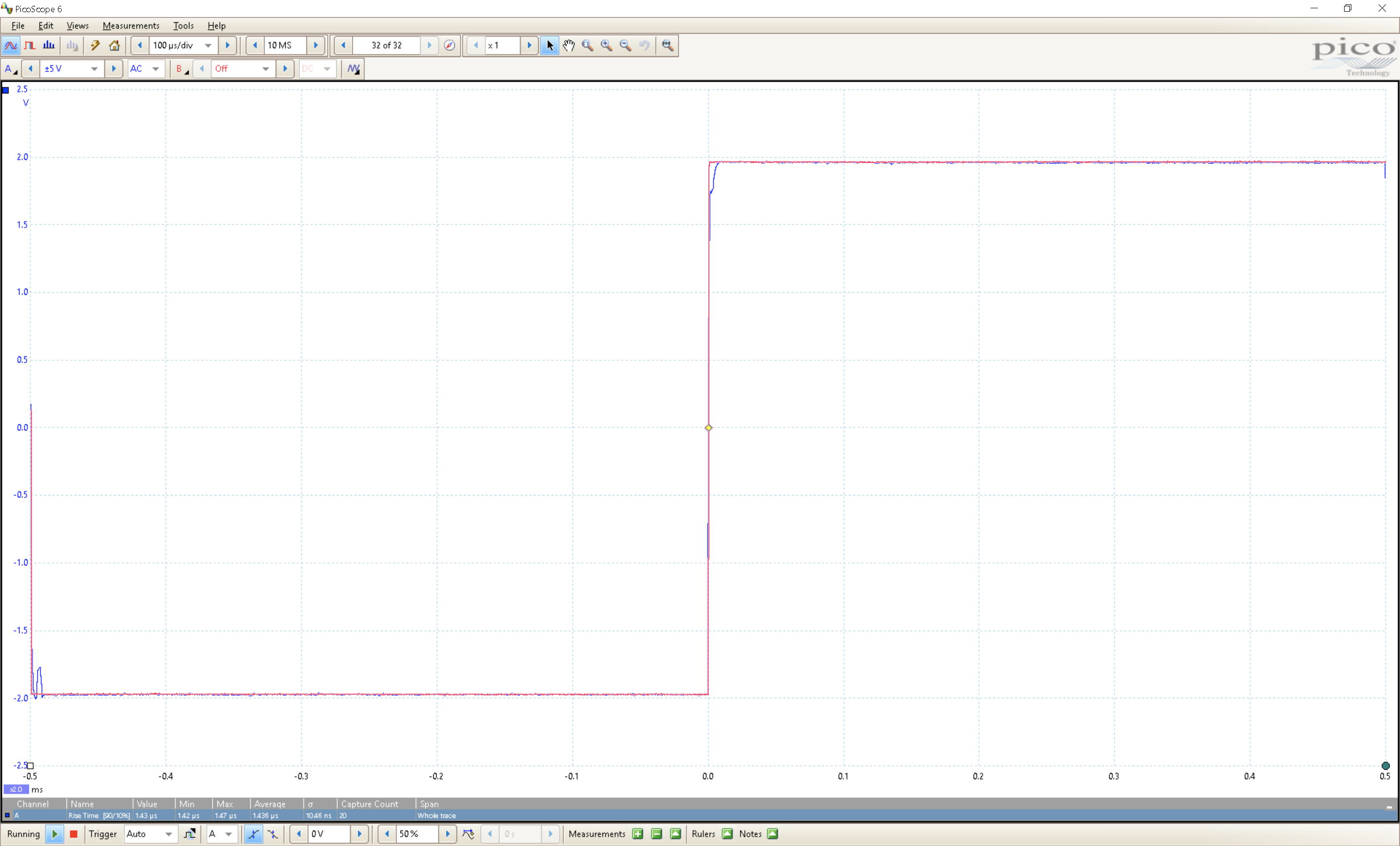
index.php


And for good measure :) here's the 1k square wave:
index.php


I didn't do any stress tests (at least not intentionally!) this time, and don't have the load simulator to measure output at greater powers.


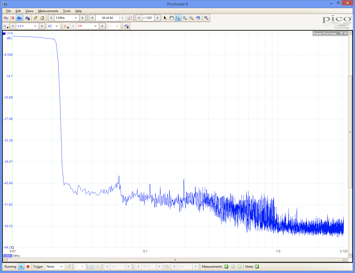
I did take some Picoscope measurements (also posted in another thread) to see what it look like above the audible range. This is playing a 10-22k sweep in REW, also at 192kHz:
index.php
 
Last edited:
OP
pkane

pkane

Master Contributor
Forum Donor
Joined
Aug 18, 2017
Messages
5,698
Likes
10,375
Location
North-East
What does distortion vs power look like?

Didn't measure this. As is I had to replace the fuses a couple of times and on the first attempt sent 0dBFS into the amp. The 20w 8Ω resistors were not very happy. They were hot to the touch for the next 20 minutes :)

I guess I could measure this up to, say, 5w in some reasonable increments.
 

SIY

Grand Contributor
Technical Expert
Joined
Apr 6, 2018
Messages
10,499
Likes
25,313
Location
Alfred, NY
If it's really Class A, the dissipation at full power won't be higher than the dissipation with no signal. Or is it the dummy load that complained?
 

maxxevv

Major Contributor
Joined
Apr 12, 2018
Messages
1,872
Likes
1,964
Would the measurements have looked better had those wires been properly twisted and shielded ? The circuit board shielded from the toroidal transformer ?
 
OP
pkane

pkane

Master Contributor
Forum Donor
Joined
Aug 18, 2017
Messages
5,698
Likes
10,375
Location
North-East
Would you like a real grown-up dummy load? I feel like I owe you for all the use I've gotten out of your software.

Kind of you to offer! Probably wouldn't be the best use of the dummy load, as I don't have that many amps to measure :) Forte just happened to be the smallest one that was easy to carry upstairs.
 
OP
pkane

pkane

Master Contributor
Forum Donor
Joined
Aug 18, 2017
Messages
5,698
Likes
10,375
Location
North-East
Would the measurements have looked better had those wires been properly twisted and shielded ? The circuit board shielded from the toroidal transformer ?

Maybe a little. Most of the harmonic distortion wouldn't change with twisted wires or shielded transformer. The mains frequency and related noise were there even when the power was turned off, so I have to believe it's not related to the active circuitry inside. Likely forming some kind of a ground loop with the rest of the test equipment (computer, Apogee interface, etc.)
 

restorer-john

Grand Contributor
Joined
Mar 1, 2018
Messages
12,703
Likes
38,838
Location
Gold Coast, Queensland, Australia
Would you like a real grown-up dummy load? I feel like I owe you for all the use I've gotten out of your software.

That's so sweet SIY. :)

You know we are in a room full of geeks when someone is offered a big boy's dummy load instead of a beer.
 

restorer-john

Grand Contributor
Joined
Mar 1, 2018
Messages
12,703
Likes
38,838
Location
Gold Coast, Queensland, Australia
And for good measure :) here's the 1k square wave:
index.php

Can you show the generator square wave and the reproduced square wave on the one trace/screen, that way we can see what the amplifier does to it.
 

NTomokawa

Addicted to Fun and Learning
Forum Donor
Joined
Jan 14, 2019
Messages
779
Likes
1,334
Location
Canada
Holy harmonics, Batman!

Very impressive-looking power block. Reminds me of the Krell KSA-50.
 

pma

Major Contributor
Joined
Feb 23, 2019
Messages
4,602
Likes
10,769
Location
Prague
1kHz sine spectrum looks rather like underbiased class AB than class A. Like typical crossover distortion. Very poor result.

It looks like if you used a soundcard to generate square wave signal? Such test would make no sense. The amp square response goes before the input, in other words input signal is delayed behind output? I do not get it.
 
OP
pkane

pkane

Master Contributor
Forum Donor
Joined
Aug 18, 2017
Messages
5,698
Likes
10,375
Location
North-East
1kHz sine spectrum looks rather like underbiased class AB than class A. Like typical crossover distortion. Very poor result.

It looks like if you used a soundcard to generate square wave signal? Such test would make no sense.

Look up some other Nelson Pass class A designs :)

https://www.audiosciencereview.com/...ass-a-power-amplifier-review.9741/post-261454

Or look up some more recent designs as measured by Stereophile. None of them will break the SINAD records (except maybe on the low side). And I like Nelson's amps and have enjoyed them for a very long time :D

The square wave was generated by REW, converted into analog by a high quality 24/192k DAC in Apogee Element24. What puzzles me is that the square wave coming out of the amp looks better than the original digital version of it from REW. I'll have to try to do this from scratch another time, as the digital waveform appears to be missing a lot of the higher frequency components compared to the one captured at the output of the amp.

The delay you are seeing is simply because I had to record digital and analog in two steps. There's no sound card.
 
Last edited:

Doodski

Grand Contributor
Forum Donor
Joined
Dec 9, 2019
Messages
21,572
Likes
21,854
Location
Canada
1kHz sine spectrum looks rather like underbiased class AB than class A. Like typical crossover distortion. Very poor result.

It looks like if you used a soundcard to generate square wave signal? Such test would make no sense. The amp square response goes before the input, in other words input signal is delayed behind output? I do not get it.
Maybe it's time for a idle current and bias calibration. Is this your first rodeo @pkane?
 
Top Bottom