• WANTED: Happy members who like to discuss audio and other topics related to our interest. Desire to learn and share knowledge of science required. There are many reviews of audio hardware and expert members to help answer your questions. Click here to have your audio equipment measured for free!

Quick Measurement: Creative Labs Soundblaster 5.1 X-Fi USB interface SB1090

pkane

Master Contributor
Forum Donor
Joined
Aug 18, 2017
Messages
5,667
Likes
10,298
Location
North-East
Through an 'accidental' purchase, I wound up with a used Soundblaster X-Fi, surround sound external card/interface. This has a 5.1 channel DAC with up to 24/96k, and a 24-bit 48K/96K two channel ADC. Model # SB1090. I don't think these are still manufactured, but are available on the used market and are really inexpensive ($25 is what I paid for this one). I believe Amir measured the replacement version of this, model SB1240.

While I have it, decided to run some quick measurements. This is on the DAC portion, need to make up new connector to test the ADC.

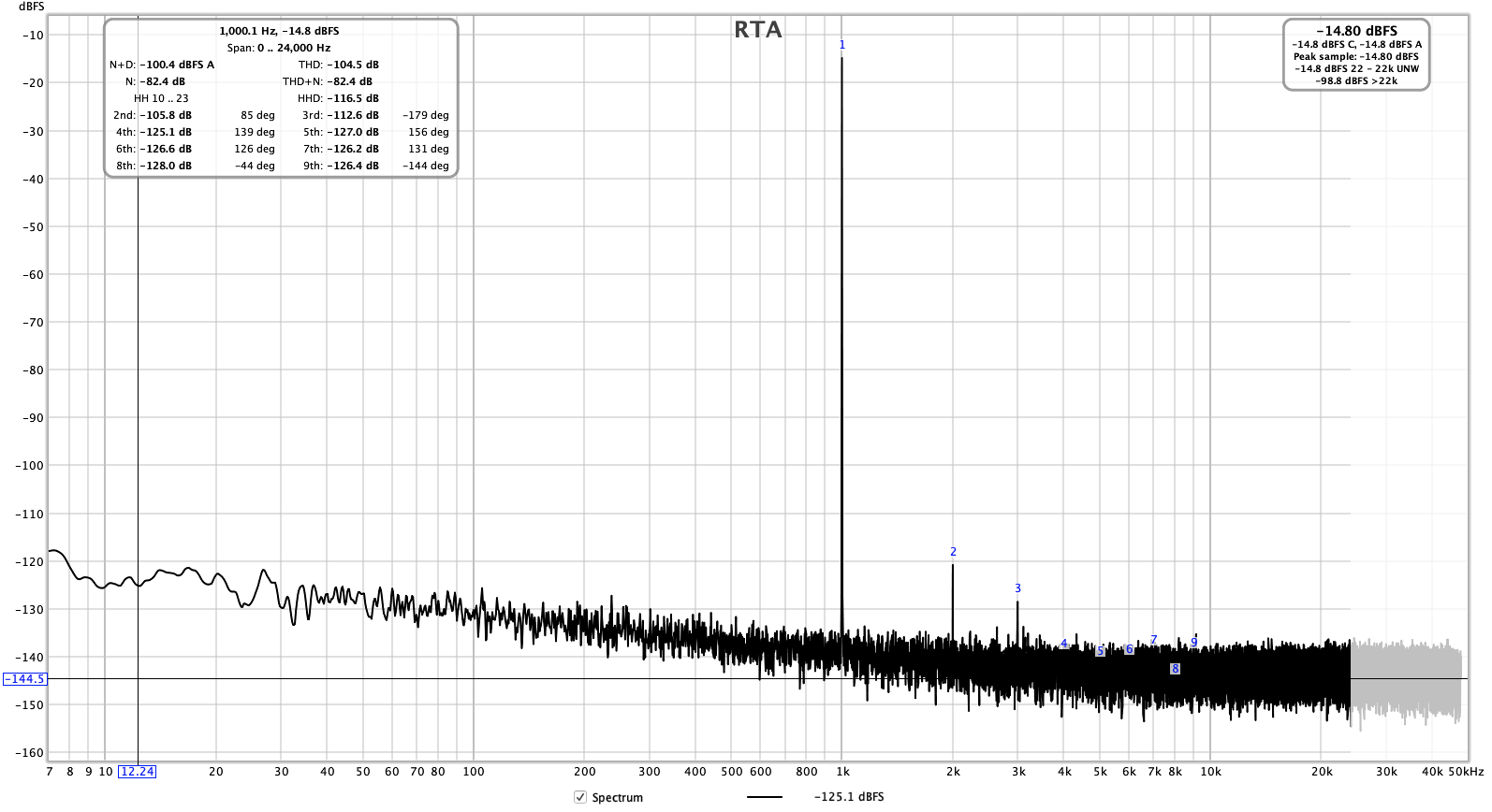
1kHz, 24/96k, 0dBFS @ 1.1v:

1k.png


EDIT: Modified the above test by powering X-Fi from a battery to eliminate ground loops and reducing level to produce a much cleaner looking result (-13dBFS @ 555mV):

index.php


Frequency response and phase:
freq.png


Impulse response (updated after redoing the capture with a battery power supply to isolate grounds):
1580177315711.png


Reconstruction filter, 48k sampling rate (updated after running the test using a battery to isolate grounds):
1580177665754.png


And at 96kHz sampling rate:

1580178273274.png


Distortion vs level:
distortion-vs-level.png


Distortion vs frequency:

distortion-vs-freq.png


Adding jitter J-Test at 44.1kHz:

1580133073887.png
 
Last edited:

bigx5murf

Addicted to Fun and Learning
Joined
Nov 6, 2018
Messages
522
Likes
343
I'm using one of these in my bedroom HTPC setup. I found mine at goodwill for $5. I'm surprised it performs so well. Mine sometimes has driver gremlins and requires a restart before it works properly.
 
OP
pkane

pkane

Master Contributor
Forum Donor
Joined
Aug 18, 2017
Messages
5,667
Likes
10,298
Location
North-East
I'm using one of these in my bedroom HTPC setup. I found mine at goodwill for $5. I'm surprised it performs so well. Mine sometimes has driver gremlins and requires a restart before it works properly.

I was impressed with what this little box could do, considering the number of channels and the built-in ADC. The headphone output, I understand, is a bit underpowered (didn’t measure it).

I didn’t have any driver issues, but then I didn’t need a driver — I was using this with a Mac. Worked without a hitch as soon as I plugged it in.
 

pma

Major Contributor
Joined
Feb 23, 2019
Messages
4,602
Likes
10,768
Location
Prague
Looks definitely like measurement error. I get this from (slightly modified) Creative USB X-Fi HD.

xfihd_loop_1kHz_A.png
 
OP
pkane

pkane

Master Contributor
Forum Donor
Joined
Aug 18, 2017
Messages
5,667
Likes
10,298
Location
North-East
Looks like slight clipping. What signal level was that, and what happens if you lower it a little?

yes, strange. I adjusted the level up and down a few dB but didn’t find any improvement. Now that you made me look more closely, THD rises right after -12dBFS, so I can try at around that point.
 
OP
pkane

pkane

Master Contributor
Forum Donor
Joined
Aug 18, 2017
Messages
5,667
Likes
10,298
Location
North-East
Well, lowering the signal level didn't seem to help a whole lot, although it did change some of the relative harmonic levels. Here's the comparison between -15dBFS @ 200mV (black) and 0dBFS @ 1.1v (red):

1580129286624.png


I'll see if I can find a way to better isolate grounds, may be by powering the X-Fi off of a battery through a split USB cable.
 
OP
pkane

pkane

Master Contributor
Forum Donor
Joined
Aug 18, 2017
Messages
5,667
Likes
10,298
Location
North-East
They both look weird because of these numerous up's and down's.

Here is for example IR of Topping D10:

View attachment 47643

I remember seeing the same "shaky" IR when my friend measured his speakers. How comes it is like that?

I suspect this is due to a fairly shallow filter with a lot of stopband ripple, but I could be wrong :)
 

Krunok

Major Contributor
Joined
Mar 25, 2018
Messages
4,600
Likes
3,067
Location
Zg, Cro
I suspect this is due to a fairly shallow filter with a lot of stopband ripple, but I could be wrong :)

I'm sorry but I don't understand: what does "shallow" mean in context of filter and what is "stopband" ripple?
 
OP
pkane

pkane

Master Contributor
Forum Donor
Joined
Aug 18, 2017
Messages
5,667
Likes
10,298
Location
North-East
I'm sorry but I don't understand: what does "shallow" mean in context of filter and what is "stopband" ripple?

Shallow = the difference between pass-band and stop-band. In this case, you can see it's only about 50dB. And you can see very large ripples in the stop-band, after the filter cut-off frequency:

index.php


For comparison, here's a filter I use in DeltaWave for low-pass filtering:

1580138080837.png
 

Krunok

Major Contributor
Joined
Mar 25, 2018
Messages
4,600
Likes
3,067
Location
Zg, Cro
Shallow = the difference between pass-band and stop-band. In this case, you can see it's only about 50dB. And you can see very large ripples in the stop-band, after the filter cut-off frequency:

index.php


For comparison, here's a filter I use in DeltaWave for low-pass filtering:

View attachment 47649

Ok, I see, thank you!

I am not sure that is the reason as what I saw with my friend's speakers IR was a room EQ lodspeaker filter so it probably didn't have any stopband at all.
 

mansr

Major Contributor
Joined
Oct 5, 2018
Messages
4,685
Likes
10,703
Location
Hampshire
Impulse response:
index.php
What did you use to record that impulse response? We're likely seeing the combination of the DAC and ADC responses, which can easily get weird. You might want to check it with an oscilloscope.
 
OP
pkane

pkane

Master Contributor
Forum Donor
Joined
Aug 18, 2017
Messages
5,667
Likes
10,298
Location
North-East
What did you use to record that impulse response? We're likely seeing the combination of the DAC and ADC responses, which can easily get weird. You might want to check it with an oscilloscope.

Here's the impulse response of the DAC/ADC loopback of my 'measurement' device (Apogee Element24):

1580139422422.png
 
Top Bottom